Averaging Options
The averaging options allow you to limit the averaging of results to only a group of elements that are considered to be bound by same feature angle or face.
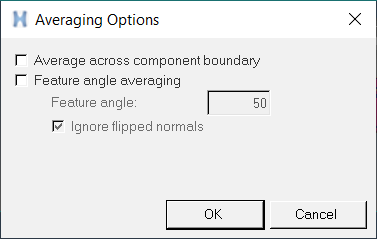
Figure 1.
- Average across component boundary
- Enables the nodal averaging across the component boundary. The contribution for a shared node will come from every component associated with that node, while all of the other averaging principles remain.
- Feature angle averaging
- Activate this option to specify the threshold value for elements to be considered as
part of the same feature by specifying a Feature angle value. All of the adjacent
elements whose normals are less than or equal to the threshold value are averaged.
The output of this contour is always corner based data (no centroid values). A feature angle average calculation example is shown below:
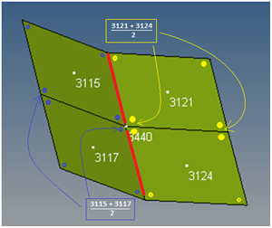
Figure 2.Result at common node 3440:- E 3115, average of corner nodes for element 3115 and 3117
- E 3121, average of corner nodes for element 3121 and 3124
- E 3117, average of corner nodes for element 3115 and 3117
- E 3124, average of corner nodes for element 3121 and 3124
- Feature angle
- Allows you to specify the value to be used in the Feature angle averaging
calculations. The default is 30 degrees. All of the elements whose normals are less or
equal to the specified threshold value are averaged. The value can range from 0 to 180
degrees.For element feature angle calculation, the current model position is used. Only shell elements feature angles are considered, therefore all solid and beam elements will be included in the averaging calculation (see the example below):
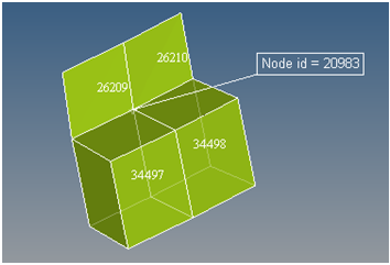
Figure 3.The result at common node 20983 = the average of corner nodes for all four elements.
- Ignore flipped normals
- This option is checked by default (for feature based averaging) to allow for any
modeling discrepancies to be disregarded. Consider the picture and description below which shows two adjacent elements whose normals are flipped as a consequence of a model setup discrepancy:
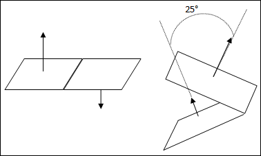
Figure 4.In the example above, the feature angle threshold for averaging is set at 30 degrees. The image on the left side has an angle between adjacent element normals close to 180 degrees and therefore does not meet the criteria of the 30 degree threshold. The image on the right has the angle between normals less than 30 degrees, and the threshold criteria for feature angle is satisfied. However, this could be a modeling discrepancy that should be accounted for, perhaps allowing the averaging of values for elements on the left image, but not allowing averaging of elements on the right image. This can be accomplished by activating the Ignore flipped normals option.
If strict adherence to the angle between adjacent element normals is to be enforced, then uncheck this option.
See the examples provided below: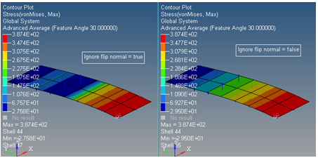
Figure 5.