Derived Load Cases
The Loadcase tool allows you to create a derived load case from other load cases, or from a combination of other load cases and simulation steps.
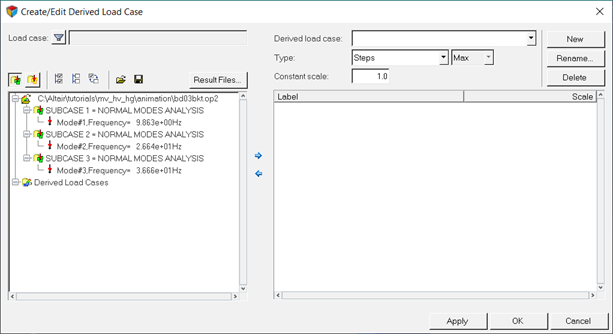
Figure 1.
- Steps
- Linear-Superposition
- Envelope
Recent enhancements have been made which involve the creation of a Linear-Superposition or Envelope loadcase composed of base and derived loadcases. Finding the minimum or maximum of envelopes, or the maximum value of a set of linear combination loadcases is now possible.
See the Envelope or Linear Superposition of Base and Derived Loadcases section for additional information.
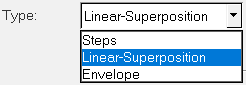
Figure 2. Type drop-down menu
In addition, the derived load cases list can be displayed by
clicking on the View Derived Load Cases icon ![]() .
.
| Use | To |
|---|---|
| Save | Save the definition of the current derived loadsteps as a configuration file. |
| Open | Import/read a previously saved derived loadstep configuration file. |
Steps
The Steps type is used to create a derived loadstep from other loadsteps. A derived loadstep can contain more than one simulation step, with scale factors optionally applied to them.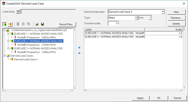
Figure 3.
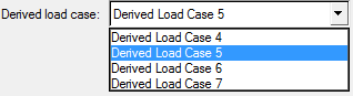
Figure 4. Select loadstep drop-down menu
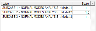
Figure 5. Example derived loadstep table
- Label
- Displays the loadstep number and the time of each simulation step.
- Scale
- Displays the scale factor that was defined for each loadstep/simulation
step.Note: The scale factor can be manually changed/edited.
Simulation steps can also be removed from a loadstep.
Linear Superposition
The Linear Superposition type is used to create a derived loadstep with only one simulation step, which is a combination of all the selected loadsteps/simulations with scale factors.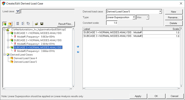
Figure 6. Create/Edit Derived Load Case dialog (with Linear-Superposition as the type and the View Load Cases icon activated)
The Loadsteps section lists all the loaded results files in the current session, as well as all the loadsteps/simulations corresponding to each result file, in a tree-like structure.
In addition, the derived load cases list can be displayed by clicking on
the View Derived Load Cases icon ![]() .
.
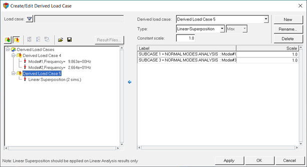
Figure 7. Create/Edit Derived Load Case dialog (with Linear-Superposition as the type and the View Derived Load Cases icon activated)
This section allows you to specify which loadstep(s), from the currently selected input file, to add to the linear combination definition.
Envelope
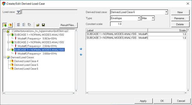
Figure 8. Create/Edit Derived Load Case dialog (with Envelope/Max as the type and the View Load Cases icon activated)
The Loadsteps section lists all the loaded results files in the current session, as well as all the loadsteps/simulations corresponding to each result file, in a tree-like structure.
- Min
- Finds the minimum values among all the selected loadsteps or simulations (weighted by the appropriate scale factors) defined within the derived loadcase.
- Max
- Finds the maximum values among all the selected loadsteps or simulations (weighted by the appropriate scale factors) defined within the derived loadcase.
- Extreme
- Finds the maximum absolute values among all the selected loadsteps or simulations (weighted by the appropriate scale factors) defined within the derived loadcase. The sign of the number is not changed however. For example, the Extreme of 5 and 10 is 10, and the Extreme of 5 and -10 is -10.
- Range
- Finds the difference between the maximum value and the minimum value among all the
selected loadsteps or simulations (weighted by the appropriate scale factors) defined
within the derived loadcase.Note: Selecting this option will disable the Envelope trace plot option in the Contour panel.
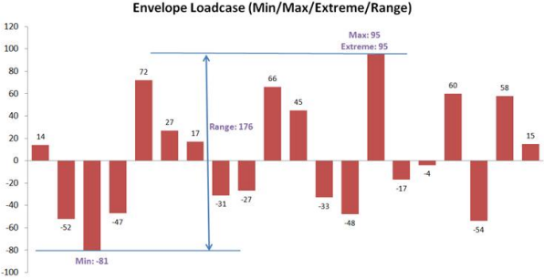
Figure 9.
When a particular layer is selected in the Contour panel, the Envelope value is obtained by cycling through all the loadsteps for that given layer, and the Min/Max/Range value is then reported. When the layer aggregate is set to Min/Max/Extreme/Average/Range, the result is calculated across all the layers including all the loadsteps defined for the Envelope.
It is possible to resolve a contour in global system. The value on the entity (element, node etc.) is first transformed into global system and then the envelope value is obtained by cycling through all the load steps for that entity.
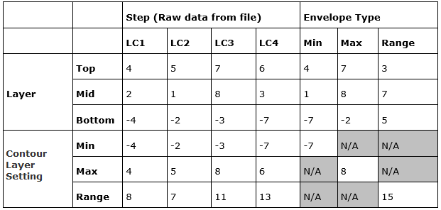
Figure 10.
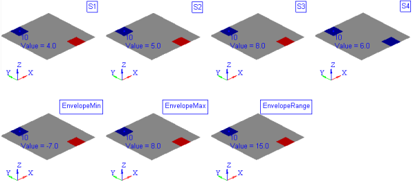
Figure 11.
Envelope or Linear Superposition of Base and Derived Loadcases
In certain use cases, it may be useful to create an envelope or a linear combination of a derived loadcase. As an example of finding the maximum of a set of linearly combined loadcases, or just finding the minimum or maximum of different envelope type loadcases. From the base loadcases provided by the solver, you can create two levels of derived loadcases (as shown in the image below):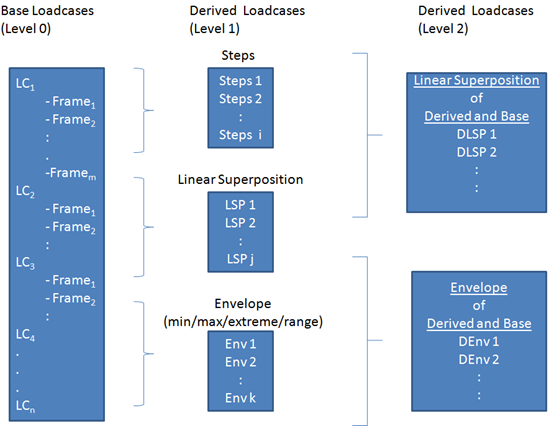
Figure 12.
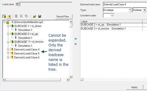
Figure 13.
Various checks are performed in order to try and prevent the creation of ill-defined derived loadcases. Among them, a recursive error is displayed when a loadcases is pointing to itself through recursion, or going through more than two levels of derived definition. The error message will be prompted with no action taken. It is also important to note that the newly created IDs for a derived loadcase (at level 2) are stored and restored from the session/report template file (and not necessarily the base loadcase IDs). In the case of envelope derived loadcases, the trace plot in the contour panel will display the derived loadcase ID where appropriate.
If loadcases from multiple result files are referenced, it is recommended that you include all the required result files prior to creating any derived loadcases. See the Update Result Files topic for additional information regarding adding result files.