Export Files
In HyperWorks Desktop exporting various file types from the selected client to another format.
During export you can write information from a HyperMesh database to many finite element formats. However, geometry data can only be written in IGES format.
Use the Custom option to export models using your own custom-built export translator, or export models using a translator provided with the HyperMesh installation but which is not directly accessible via the default Export pull-down menu.
Export Models
Export model files.
-
Export a model in the following ways:
- From the menu bar, click .
- From the Standard toolbar, click
 (Export
Model).
(Export
Model).
The Export - Model tab opens. -
Define model export options by clicking
 to the left of
Export Options.
to the left of
Export Options.
Model Export Options
Options used to export model files.
- Write titles as notes
- Export HyperMesh titles as HyperView notes. By default, HyperMesh titles are not exported as HyperView notes.
- Write results
- For supported entities and result contours, this option writes the displayed results to an H3D file. If no supported result contour is displayed, this option is ignored.
- Prompt before overwrite
- Display prompt before overwriting information.
Export Solver Decks
Export solver input files.
HyperMesh uses templates to create the analysis input decks for finite element solvers. You can modify the existing templates to support a desired feature or create a new template to support another analysis code. HyperMesh templates can be used to create model summaries and perform some analysis calculations. You can also use the templates to perform complex editing or data manipulation tasks.
The Media (*.bif) is also supported for nodes, elements (mass, beam, tria3, quad4, tetra4, tetra10, penta6, penta15, hexa8, hexa20), and sets (nodes, elements) in the LS-DYNA user profile.
-
Export a solver deck in the following ways:
- From the menu bar, click .
- From the Standard toolbar, click
 (Export Solver Deck).
The Export - Solver Deck tab opens. -
Define Solver Deck Export Options by clicking to the left of Export
Options.
Solver Deck Export Options
Options used to export solver decks.
- Export
- Type of entities to export.
- All
- Export all entities in the current database.
- Custom
- Select entities to export from the selected file.
- Displayed
- Export only the entities that are currently displayed.
- Entities that have a display state and/or a mask state are displayed on the screen are exported. This includes elements, loads, equations, systems, vectors, groups, components, blocks, contactsurfs, multibodies, ellipsoids, mbplanes, mbjoints, assemblies, control cards (that are enabled), loadcols, systemcols, vectorcols, and connectors.
- Entities that do not have a display state and/or a mask state are exported if at least one of the entities it contains is displayed. For example, entity sets do not have a display state (on/off). If an entity set contains elements and some of the elements are displayed, the set is exported. However, the contents of the set are limited to the displayed portion only. If this set contains 20 elements, five of which are displayed and remaining turned off, the exported set will contain only five elements. Entities in this category include: entity sets, output blocks, loadsteps, control vols, and beamsect cols.
- Entities that do not have a display state and/or a mask state are exported if the entity is being used by a displayed entity. For example, materials do not have a display state, but if a displayed component or element uses it, that material is exported. Entities in this category are: nodes, materials, properties, entity sets, and curves.
- Sometimes entities that are not displayed are exported anyway, if the entity is referred to by another entity that is displayed. For example, when a vector is turned off, but is used in defining the orientation of a beam element, the vector will be exported in order to export the beam element correctly. Entities in this category are: vectors, systems, beamsections, multibodies, and components.
- Any entity that is used or required by an attribute of a displayed entity is also exported. For example, if a material is defined as an attribute on an element, that material is exported. All entities in the HyperMesh database belong to this category.
- Any entity that points to a displayed entity is exported. Tags and titles belong to this category.
- Solver options
- Define Solver Export Options export settings by clicking Select Options.
- Comments
- Select the type of comments to write upon export.
- HyperMesh
- Write HyperMesh comments upon export. When unchecked, HyperMesh comment cards are ignored.
- Connectors
- Export all of the connectors in the model. This operation appends the master connector file xml data to the end of the solver input file as solver comments and thus does not effect the operation of the solver. This operation can remove the necessity to perform a FE-absorb on a imported model since the connector information is retained in the solver input file.
- Part Assemblies/Parts
- Export an xml comment block containing HyperMesh part assemblies/parts, along with PDM metadata.
- Include files
- Method for exporting includes.
- ID Rules
- Export ID management rules defined in the ID Manager as an XML block at
the end of each Include file. Restriction: Available when Include files is set to Preserve.
- Prompt warnings of ID Conflicts
- Display prompt when there are ID conflicts.
- Prompt to save invalid elements
- Display prompt to save invalid elements.
- Prompt before overwrite
- Display prompt before overwriting information.
Solver Export Options
Supported solver export options.
Access solver export options by clicking Select Options, next to Solver Options in the Export - FE Models tab.
OptiStruct and Nastran
- Remove ‘E’ from real values
- OptiStruct and Nastran solvers do not require explicitly writing an E to recognize the proper exponent of a real number, and removing the E allows one more digit of precision to be included. For example, -1.12E-7 becomes -1.123-7.
- Zero tolerance
- With this option, any real numbers in the model whose absolute value is less than specified here will be written out as zero. For example, if Zero tolerance = 1.0E-12, it means all real values from -1.0E-12 to 1.0E-12 will be exported as 0.0.
- Auto-organize NSM
- When turned on, this option automatically collects all non-structural mass entities [NSM1, NSML1] into a NSMADD loadcollector. This loadcollector is then automatically referenced in the NSM GLOBAL_CASE_CONTROL control card. As long as Auto-organize NSM is checked on, it will update the NSMADD loadcollector on every export and if you delete all NSM* cards, this option will delete NSMADD and case control reference along with it.
- Auto adjust RBE3 0.0 weight factor
- When turned on, HyperMesh will change any 0.0 weight factors on RBE3 elements to the specified small value. This adjustment is done in the exported solver deck only, and the original model values in the current HyperMesh session will not be modified.
- Compress Nodes/Element Sets
- When turned on, all node sets and element sets in the model are exported with the THRU statement.
- Free Format Export
- (OptiStruct only): When turned on, the model will be exported in free format (comma separated format). This option supersedes other export templates like standard format and long format.
Permas
While rigid and rbe3 elements use the same ID pool in HyperMesh, equations and groups have separate ones. During creation, it is possible to use this situation to create duplicate IDs for MPCs as well. To resolve this, during export a solver option is available in the Export tab to renumber MPCs if duplicate IDs are present (Renumber MPCs if IDs are duplicated). This option will check for the highest rigid/rbe3 ID and renumber equation entities accordingly. Groups are not included in the renumbering functionality as contact IDs would be affected by renumbering.
The Export to gzip compressed file (.gz) option allows you to export files to .gz file format (gzip), which is Permas compressing tool. This format is directly read into their solver.
Abaqus
- Export Entities With Quotes
- Abaqus does not support special characters or staring with numbers in entity names. In order to retain entity names during export, quotes can be added to entity names. By default, entities with quotes are not exported in the solver deck. Select this checkbox to export entities with quotes in the solver deck.
- Export *NMAP keyword
- Exports the solver deck with the *NMAP keyword (default). Clearing this checkbox exports a flat solver deck without the *NMAP keyword.
- Auto adjust RBE3 0.0 weight factor
- When enabled, HyperMesh changes any 0.0 weight factor on RBE3 elements to the specified small value. This adjustment is only done in the exported solver deck. The original model values in the current HyperMesh session will not be modified.
- Export Id's
- Each entity is assigned to an ID when it is imported into HyperMesh. In cases of Abaqus Interface, when you export the solver deck from HyperMesh, entity IDs will not be retained. By activating the Export ID’s option, entities will be assigned a range of IDs that are specific to each entity during export. Since more than one entity may exist, an alphabetic prefix is assigned to each entity in order to avoid a duplicate ID conflict.
LS-DYNA
- Remove Numerical Suffix from Duplicate Titles
- Removes numerical suffixes from duplicate titles.
- Activate Transformations after Export Operation
- Activates transformations after export operation.
- Repeat Keyword Titles
- Repeats keyword titles for each instance of the card.
- Auto create property for COMPS with TETRA4/PENTA6/HEX8 elements
- Creates properties for components that have TETRA4, PENTA6, and HEX8 elements.
- Remove include file reference based on export status
- Removes include file reference based on export status.
PAM-CRASH 2G
- Activate Transformations after Export Operation
- Activates transformations after export operation.
Entity Export Behavior
Overview of how entities are exported from HyperWorks Desktop.
Free Nodes
- Nodes associated to elements are always exported. Element export is controlled by the component/group export state that the element resides in.
- Nodes associated to node dependent systems are always exported. System export is controlled by the systemcol export state that the system resides in.
- Nodes associated to node dependent vectors are always exported. Vector export is controlled by the vectorcol export state that the vector resides in.
- Nodes associated to rigid wall's base node are always exported. Rigid wall export is controlled by the group export state that the rigid wall resides in.
- Nodes on card images of exported entities are exported with those entities. Entity export is controlled by the export state of that entity (all entities).
- Temporary nodes are always exported.
- Nodes with a non-empty card image are always exported, for example SPOINT.
Assembly
- Do Not Export: Does not export assembly comments. If there are components defined within an assembly that is set to Do Not Export, then these component are also not exported. If the same component is referenced in multiple assemblies which have different export statuses, then you must also verify the export status for each component to assure its final export status.
- Export: Export assembly comments. When changing from Do Not Export to Export, it sets any components defined within that assembly to Export, regardless if that component exists in multiple assemblies.
Component
- Do Not Export: Does not export component comments, component definitions, nodes (see below), elements, connector comments, points, lines, surfaces, and solids within that component.
- Nodes within components can be of two types: Internal nodes and Boundary nodes. Internal nodes are not shared with any other component. Boundary nodes are shared with other components. Internal nodes "export" is based solely on their component export state. Boundary nodes do not export, if all components which they reside in are set to Do Not Export. If a boundary node exists in any one component set to Export, then that boundary node is also exported.
- Export: Export component comments, component definitions, nodes (internal and boundary), elements, connector comments, points, lines, surfaces, and solids within that component.
Load Collector
- Do Not Export: Does not export LoadCollector comments, loads, or equations within that LoadCollector
- Export: Exports LoadCollector comments, nodes/elements attached to loads/equations, loads, and equations within that LoadCollector
System Collector
- Do Not Export: Does not export SystemCollector comments or systems within that SystemCollector
- Export: Exports SystemCollector comments, nodes attached to systems, and system definitions within that SystemCollector
Vector Collector
- Do Not Export: Does not export VectorCollector comments or vectors within that VectorCollector
- Export: Exports VectorCollector comments, nodes attached to vectors and vector definitions within that VectorCollector
BeamSection Collector
- Do Not Export: Does not export BeamSectionCollector comments or BeamSection comments within that BeamSectionCollector
- Export: Exports BeamSectionCollector comments and BeamSection comments within that BeamSectionCollector
MultiBody
- Do Not Export: Does not export Multibody comments, ellipsoids, MultibodyPlanes or MultibodyJoints within that Multibody Collector
- Export: Exports Multibody comments, nodes attached to ellipsoids/MultibodyPlanes/MultibodyJoints, ellipsoids, MultibodyPlanes and MultibodyJoints within that Multibody Collector
LoadStep
- Do Not Export: Does not export LoadStep comments or LoadStep definitions of the LoadStep
- Export: Exports LoadStep comments and LoadStep definition of the LoadStep. The LoadStep export status has NO effect on the export behavior of LoadCollectors, OutputBlocks, or groups associated with the LoadStep.
Output Block
- Do Not Export: Does not export OutputBlock comments or OutputBlock definitions of the OutputBlock
- Export: Exports OutputBlock comments and OutputBlock definitions of the OutputBlock
Card
- Do Not Export: Does not export card comments or card definition of the card. This is same as "Disable" on the Card panel.
- Export: Exports card comments and card definitions of the card
Property
- Do Not Export: Does not export property Comments or property definitions of the property
- Export: Exports property comments and property definitions of the property
Material
- Do Not Export: Does not export material comments or material definition of the material
- Export: Exports material comments and material definition of the material
Sets
- Do Not Export: Does not export set comments or set definitions of the set
- Export: Exports set comments and set definitions of the set
Blocks
- Do Not Export: Does not export block comments or block definitions of the block
- Export: Exports block comments and block definitions of the block
Tags
- Do Not Export: Does not export tag comments or tag definitions of the tag
- Export: Exports tag comments and tag definitions of the tag
Titles
- Do Not Export: Does not export title comments or title definitions of the title
- Export: Exports title comments and title definitions of the title
Plots
- Do Not Export: Does not export plot comments, plot definitions, curve comments, or curve definitions associated to the plot
- Export: Exports plot comments, plot definitions, curve comments, and curve definitions associated to the plot
Contact Surface
- Do Not Export: Does not export ContactSurface comments or ContactSurface definitions of the ContactSurface
- Export: Exports comments and nodes/elements associated to ContactSurface or ContactSurface definitions of the ContactSurface
Group
- Do Not Export: Does not export group comments or group definitions of the group
- Export: Exports group comments, nodes/elements associated with Group and group definitions of the group
Sensor
- Do Not Export: Does not export sensor comments or sensor definitions of the sensor
- Export: Exports sensor comments and sensor definitions of the sensor
Control Volume
- Do Not Export: Does not export ControlVolume comments or ControlVolume definitions of the ControlVolume
- Export: Exports ControlVolume comments and Control Volume definitions of the ControlVolume
Element
- Controlled by component collector export status
Connector
- Controlled by component collector export status
Load
- Controlled by load collector export status
Equation
- Controlled by load collector export status
System
- Controlled by system collector export status
Vector
- Controlled by vector collector export status
Point
- Controlled by component collector export status
Line
- Controlled by component collector export status
Surfaces
- Controlled by component collector export status
Solid
- Controlled by component collector export status
Beam Section
- Controlled by beam section collector export status
Ellipsoids
- Controlled by multibody collector export status
Multibody Planes
- Controlled by multibody collector export status
Multibody Joints
- Controlled by multibody collector export status
Load Summary Templates
Summary templates are templates that you can use to count elements or categorize properties.
These templates do not create solver input, but are used to gain a quick overview of a model or to find specific solver-related information about a model.
- Calculating the center of gravity
- Listing components associated with materials
- Checking for errors that would cause an input deck to be rejected by a solver
For more information about creating and using a summary template, see the Summary panel.
- From the menu bar, click .
- Click Load.
- Browse to your solver specific folder and click the name of your solver. When using a summary template for the first time, jump to step 4 thereafter.
- Click on the summary template to use and click Open.
- Click browse... and select an output file from the Save file Browser to store the summary.
- Click Save.
- Select all or displayed to output all or only some of the contents of the deck.
- Click summary.
Supported Summary Templates
Overview of the Summary Templates supported by the solver interfaces.
ANSYS
| Path Within HyperWorks Installation | Description |
|---|---|
| .../templates/summary/ansys/components | Reviews components of the current database containing 1D, 2D and 3D elements |
| .../templates/summary/ansys/elements | Reviews all elements of the current database |
| .../templates/summary/ansys/loads | Reviews the loads of the current database |
| .../templates/summary/ansys/ctr_of_gravity | Calculates the model’s center of gravity |
| .../templates/summary/ansys/mom_of_inertia | Determines area properties |
| .../templates/summary/ansys/materials | Reviews material properties of the current database |
| .../templates/summary/ansys/id_info | This reviews the minimum and maximum IDs of nodes, elements, components, materials, properties, and so on. |
LS-DYNA
| Template | Description |
|---|---|
| elements | Provides a listing of element types and the number of each type contained in the current model. It also indicates the total number of elements in the model. |
| errorcheck | Gives a brief overview of problems that exist in the model. |
| sharedrigids | Highlights the elements with nodes that are shared among rigids. |
| ctr_of_gravity | Calculates each part’s center of gravity and the model's center of gravity based on the procedure described in the Mass Calculations section. |
| components | Describes the components and their properties contained in the model. The template lists the name, ID, property name and ID, material name and ID, mass, nodal mass added to each part, thickness and numbers of elements in each part. The mass is calculated using the same procedure as the mass panel. |
| mom_of_inertia | Calculates each component's and the model’s moment of inertia based on the procedure described in the Mass Calculations section. |
Both the errorcheck template and sharedrigids template check for shared rigids, but the template highlights only the second element that uses a node. If an element in a rigid material is sharing a node with another rigid, only the first element in that component is highlighted.
- Elements in components pointing to a *SECTION card of the wrong type
- Zero or negative thickness
- Rigid elements, components, or interfaces sharing nodes
- Components do not have a *SECTION card selected
- Components do not have a necessary *PART card defined
- Components do not have a material selected
Marc
| Template | Description |
|---|---|
| ctr_of_gravity | Calculates the center of gravity of the model. |
| mom_of_inertia | Calculates the moment of inertia of each component of the model as well as the moment of inertia of the entire model. |
| show_normals2d.sum | Shows the orientation of a 2-D rigid body which consist of plot elements of type FACET_2. |
| reverse_normals2d.sum | Reverse the orientation of a 2-D rigid body. |
Nastran
| Template | Description |
|---|---|
| elements | Summarizes the number of each element type in the current HyperMesh database. |
| loads | Summarizes the forces and moments applied to the current model. |
| ctr_of_gravity | Calculates the center of gravity of the model. |
| errorcheck | Summarizes some common model errors. |
| mom_of_intertia | Calculates the mass moment of inertia of each component of the model as well as the mass moment of inertia of the entire model. The mass moment of inertia of the entire model is presented in matrix format. |
| components | Summarizes the component information in the current HyperMesh database. |
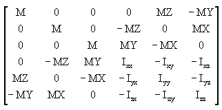
Figure 1.
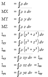
Figure 2.

Figure 3.
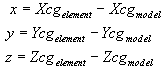
Figure 4.
PAM-CRASH 2G
Summary template directory: $hmdir/template/summary/pamcrash2g
Summary templates with a _txt appendix, for example, components_txt, can be used to export summary template information to a text file only.| Template Name | Description |
|---|---|
| ctr_of_gravity | Lists the component and model center of gravity. |
| moment_of_inertia | Lists the moment of inertia for components and for the model. |
| components | Lists the components with ID, thickness, mass, and number of
elements. You can write the result data in other units using the command, "*uservariableset("#MASS_UNIT_FACTOR",[1.0])" at the beginning of the components file in the include directory of the summary files. All calculated values are multiplied with this factor before being written. You can change this value for your own purpose. Non-structural masses are also listed in addition to the structural masses. |
| elements | Lists the elements with their PAM-CRASH 2G equivalent keywords. |
| groups | Lists the groups with their PAM-CRASH 2G equivalent keywords, type, and ID. |
| materials | Lists the materials and their corresponding elements. The model mass is calculated for each material. Lumped masses and type 3 rigid bodies are also listed. |
| sensor | Lists the sensors and their PAM-CRASH 2G keywords and types. |
| property | Lists the number of airbags, friction card, gaspec definitions, and rupture models. |
| find_cnodes | Displays the CNODEs as temporary nodes. |
| id_info | Lists the IDs and ranges of used HyperMesh entities. |
| nsmas | Lists the non-structural masses in the model together with the attached components. |
Permas
| Template | Description |
|---|---|
| elements | Summarizes the number and type of elements in the current HyperMesh model for a Permas analysis. |
| ctr_of_gravity | Calculates the center of gravity of the model. |
| mom_of_inertia | Calculates the moment of inertia of each component of the model, as well as the moment of inertia of the entire model. |
OptiStruct
The optistruct template generates OptiStruct input decks.
The optistructlf template generates OptiStruct input decks using the long format for CELAS, CONM2, FORCE, GRID, MAT1, MAT2, MAT8, MAT9, MOMENT, MPC, PBEAM, PBEAML, PCOMP, PCOMPG, PBARL, PROD, and PSHELL Bulk Data Entries.
DVGRID Bulk Data Entries are written in long format with both templates.
| Template | Description |
|---|---|
| components | Summarizes the name, number, material, mass, and number of elements for each component in the current HyperMesh database. |
| constraints | Summarizes the name, number, response, lower, and upper bounds for each constraint in an optimization problem defined in the current HyperMesh database. |
| ctr of gravity | Calculates the center of gravity of the model. |
| elements | Summarizes the number of each element type in the current HyperMesh database. |
| loads | Summarizes the forces and moments applied to the current model. |
| mom of inertia | The mom_of_inertia template calculates the moments of inertia of the model. The mass moment of inertia of the entire model is presented in matrix format. |
| errorcheck | Summarizes the model errors. |
| responses | Summarizes the name and type of responses in an optimization problem defined in the current HyperMesh database. |
Figure 5.
Figure 6.
Figure 7.
Figure 8.
Export HyperView Solver Decks
Export deformed shapes as an Abaqus, DynaKey, OptiStruct/Nastran or STL model.
-
Export a solver deck in the following ways:
- From the menu bar, select .
- From the Standard toolbar, click (Export Solver
Deck).
The Export Deformed Shape dialog opens.
Export Geometry
Export a CAD file.
-
Import geometry in the following ways:
- From the menu bar, click .
- From the Standard toolbar, click
 (Export
Geometry).
(Export
Geometry).
The Export - Geometry tab opens. -
Define CAD export options by clicking to the left of
Export Options.
CAD Export Options
CAD writers provide options for processing data during export.
Some of these options are available from the Export browser, while other options are accessed only from each writer's _writer.ini file.
- Version
- Corresponds to the @Version option.
- File mode
- Corresponds to the @FileMode option.
- Export
- Corresponds to the @Export option.
- Source units
- Corresponds to the @SourceUnits option.
- Target units
- Corresponds to the @TargetUnits option. When Target units value is selected as Source units (default), Target units is assigned a value from Source units and used during export.
- Output Loop
- Corresponds to the @OuterLoop option.
- Layers
- Corresponds to the @LayersMode options.
- Geom mode
- Corresponds to the @GeometryMode option.
- Topo mode
- Corresponds to the @TopologyMode option.
- Assem mode
- Corresponds to the @AssemblyMode option.
- Naming mode
- Corresponds to the @WriteMetaDataAsName and @WriteNameFrom options.
- User defined
- Additional options not explicitly exposed in the GUI, in the form option1_name=option1_value, option2_name=option2_value, and so on. If an option is also exposed in GUI is mentioned in this field, the value of this field prevails.
- Name from representation
- Corresponds to the @NameFromRepresentation option.
- Optimize for CAD
- Corresponds to the @OptimizeForCAD option.
- Prompt before overwrite
- Prompts you if the specified file name already exists and will be overwritten.
Export BOMs
Export bill of material files.
-
Export BOMs in the following ways:
- From the menu bar, select .
- From the Standard toolbar, click
 (Export BOM).
The Import - BOM tab opens. -
Define BOM export options by clicking to the left of Export
Options.
- To display a prompt if the filename already exist and will be overwritten upon export, select the Prompt before overwrite checkbox.
- To save a HyperMesh binary file that contains the model hierarchy and the currently loaded representations, and attach a representation to the top level Part Assembly, select the Save Monolithic HM binary file.
Export Curves
Export plot data in several different formats so that it can be read by other software applications.
Export templates can be added to the Export Curves dialog using the *AddExportFormat() statement in the preference.mvw file.
Only curves that are turned on are exported. Any curves that are currently turned off within a plot are not exported.
-
Export curves in the following ways:
- From the menu bar, select .
- From the Standard toolbar, click
 (Export Curves).
The Export Curves dialog opens.
Export Markers
Export marker files from MediaView.
-
Export markers in the following ways:
- From the menu bar, select .
- From the Standard toolbar, click
 (Export Markers).
The Export Markers dialog opens.
Export Connectors
Export connector files.
-
Export connectors in the following ways:
- From the menu bar, select .
- From the Standard toolbar, click
 (Export
Connectors).
(Export
Connectors).
The Export - Connectors tab opens. -
Define Connector Export Options by clicking to the left of Export
Options.
- 0D: Spotweld, bolt, screw, gumdrop, clinch, rivet (blind, self-piercing, solid, swop), robscan, contact_list, threaded connection, heat stake, clip, nail
- 1D: Sequence connection 0D (spotweld, gumdrop), seamweld (butt_joint, corner weld, edge weld, i_weld, overlap weld, y-joint, k-joint, cruciform joint, flared joint), adhesive-line, hemming, contact list
- 2D: Adhesive face
- Custom attributes are managed.
- APPDATA can be optionally exported within the xMCF xml.
- FEMDATA can be optionally exported within the xMCF xml.
Connector Export Options
Supported connector export options.
- Export
- Specify which connectors to export.
- All
- Export all of the connectors in the model.
- Displayed
- Export only the connectors that are currently displayed in the modeling window.
- Include metadata
- Export the metadata information.
- Include bolt dynamic vector
- Convert Links
- Export as Common Format
- Prompt before overwrite
- Display a warning message before a file is overwritten during export.
Export Table CSV
Export a comma separated value file.
TableView supports multiple lines of data in a single cell. To add a line break, press Alt + Enter. In TableView, the Conditional Formatting and the Cell Data panels are disabled if you select a cell that contains multiple lines or if you press Alt + Enter.
-
Export a CSV file in the following ways:
- From the menu bar, select .
- From the Standard toolbar, click
 (Export Table CSV).
HyperMesh Comments
If you insert special comment cards into your input deck, you can provide HyperMesh with additional information about the colors and names of entities. You can also use comments to preserve information that is not supported by a particular solver, for example, assemblies or system references.
These comments are written to analysis decks by most HyperMesh templates.
HM_ASSEM
Import comment to sort and organize entity types into HyperMesh.
Syntax
HM_ASSEM id
Type
HyperMesh Comments
Input
- entity_type
- ASSEM, COMP
- id
- Unique entity type identification number.
Supported Solvers
ANSYS
HM_COMP_BY_PROP
Import comment to sort and organize entity types into HyperMesh.
Syntax
HM_COMP_BY_PROP name, color_id
Type
HyperMesh Comments
Input
- name
- A name given by you to help organize the model or describe the entity.
- color_id
- A color identification number from the HyperMesh color palate.
Supported Solvers
Abaqus
HMASSOC
Associate an existing node to an existing surface.
Syntax
HMASSOC node_id, surf_id, index
Type
HyperMesh Comments
Input
- node_id
- The ID of the node to be associated.
- surf_id
- The surface to which the node will be attached.
- index
- The position that the node holds in the order of the surface.
Supported Solvers
N/A
HMASSEM
Import comment to sort and organize entity types into HyperMesh.
Syntax
HMASSEM id, color_id, name
Type
HyperMesh Comments
Input
- id
- Unique entity type identification number.
- color_id
- A color identification number from the HyperMesh color palate.
- name
- A name given by you to help organize the model or describe the entity.
Supported Solvers
Abaqus
Nastran
PAM-CRASH 2G
HMASSEM_COMP_ID
Import comment to sort and organize entity types into HyperMesh.
Syntax
HMASSEM_COMP_ID compid(s)
Type
HyperMesh Comments
Input
- compid(s)
- A list of identification numbers.
Supported Solvers
Abaqus
Nastran
PAM-CRASH 2G
HMASSEM_ID
Import comment to sort and organize entity types into HyperMesh.
Syntax
HMASSEM_ID assembly id(s)
Type
HyperMesh Comments
Description
- assembly id(s)
- A list of identification numbers.
Supported Solvers
Nastran
HMBEAMSEC
Import comment to sort and organize property types and info into HyperMesh.
This Comment appears above /PROP/BEAM & /PROP/TRUS definitions. When reading an input deck that includes these comments, HyperMesh takes the Ixx,Iyy & AREA values from the HyperBeam comments definition.
If you want to edit the card image values for such property cards in a text editor instead of using HyperMesh, then this comment has to be deleted. Otherwise, the Ixx, Iyy and AREA values present in these Prop card definitions are not taken into consideration, but instead the values from the HyperBeam comments Association definitions, i.e. data following ##HMNAME BEAMSECTS, are taken.
Syntax
HMBEAMSEC type, prop_id, beamsec_id
Type
HyperMesh Comments
Input
- type
- PBARASSOC, PBARLASSOC, PBEAMASSOC, PBEAMINTASSOC, PBEAMLASSOC, PBEAMLINTASSOC, PRODASSOC, PTUBEASSOC, PWELDASSOC
- prop_id
- Unique property identification number.
- Beamsec_id
- A beam section identification number.
Supported Solvers
OptiStruct
Radioss
ANSYS
PAM-CRASH 2G
Permas
HMBEGINDOC
Import comment that indicates the beginning of the model documentation into HyperMesh.
The $HMBEGINDOC card indicates the beginning of card used for model documentation. Any number of comment lines can be placed after this line. The end of this block is indicated by a $HMENDDOC statement. Only one model documentation block is allowed per model. Upon import, the comments within the block are placed in the control card “Model Documentation”.
Syntax
HMBEGINDOC Comment 1, Comment 2, Comment 3, HMENDDOC
Type
HyperMesh Comments
Input
- Comment 1, 2, 3, and so on.
- <Any text entered>
Supported Solvers
OptiStruct
PAM-CRASH 2G
HMCOMP
Import comment to sort and organize entity types into HyperMesh.
Syntax
HMCOMP id, name color_id
Type
HyperMesh Comments
Input
- id
- Unique entity type identification number.
- name
- A name given by you to help organize the model or describe the entity.
- color_id
- A color identification number from the HyperMesh color palate.
Supported Solvers
Radioss
PAM-CRASH 2G
HMCONT
Continuation card for the HMBEAMSEC card.
Syntax
HMCONT id, set_id,name
Type
HyperMesh Comments
Input
- id
- Unique entity type identification number.
- set_id
- Unique entity type identification number.
- name
- A name given by you to help organize the model or describe the entity.
Supported Solvers
LS-DYNA
PAM-CRASH 2G
HMCURVE
Preserves the style information for load curves.
Syntax
HMCURVE line_type, marker_type, title
TYPE
HyperMesh Comments
Input
- line_type
- A five-character integer that describes the style of the line, such as solid and dashed.
- marker_type
- A five-character integer that describes the style of the point marker on the curve, such as square and round.
- title
- An 80-character string used to save the label given to the curve.
Supported Solvers
OptiStruct
Radioss
Abaqus
LS-DYNA
HMDB
Points to a material database file for the solver.
Syntax
HMDB entitytype, id, name
Type
HyperMesh Comments
Input
- entity_type
- ASSEM, BEAMSECTCOL, BEAMSECTCOLS, BEAMSECTS, BLOCKS, BLOCKS, CGAPG, COMP, CONNECTOR, CONTACTSURF, CONTROLVOL, CSURF, CURVE, CWELD, DDVAL, DEQUATIONS, DESVARS, DLINKS, DOBJREF, DVPRELS, GROUP, LOADCOL, LOADSTEP, MAT, METADATA, OBJECTIVES, OPTICONSTRAINTS, OPTICONTROLS, OPTIDSCREENS, OPTITABLEENTRS, OUTPUTBLOCKS, PLOT, PROP, SENSOR, SETS, SHAPE, SYSCOL, VECTORCOL
- id
- Unique entity type identification number.
- name
- A name given by you to help organize the model or describe the entity.
Supported Solvers
OptiStruct
Radioss
Abaqus
ANSYS
LS-DYNA
Nastran
PAM-CRASH 2G
Permas
And other miscellaneous solvers
HMDISPLAY
Defines the base location of a velocity load in HyperMesh.
Syntax
HMDISPLAY type, base_location_x, base_location_y, base_location_z
Type
HyperMesh Comments
Input
- type
- LOCATION
- base_location_x
- X location of the grid for the display.
- base_location_y
- Y location of the grid for the display.
- base_location_z
- Z location of the grid for the display.
Supported Solvers
Abaqus
HMDPRP
Import comment to sort and organize design properties into HyperMesh.
Syntax
HMDPRP elements, ids
Type
HyperMesh Comments
Input
- elements
- A list of elements.
- IDs
- IDs
Supported Solvers
Abaqus
HMENDDOC
Import comment that indicates the end of the model documentation into HyperMesh.
The $HMENDDOC card indicates the end of a card used for model documentation. Any number of comment lines can be placed before this line. The beginning of this block is indicated by a $HMBEGINDOC statement. Only one model documentation block is allowed per model. Upon import, the comments within the block are placed in the control card “Model Documentation”.
Syntax
HMENDDOC
Type
HyperMesh Comments
Input
N/A
Supported Solvers
OptiStruct
PAM-CRASH 2G
HMENT
Preserves the ADMASS card upon import in Radioss.
Syntax
HMENT elem_id, vis_nod, node_id
Type
HyperMesh Comments
Input
- elem_id
- Element identification number
- vis_nod
- node_id
- Node_id
Supported Solvers
OptiStruct
HMERROR
Export comment that detects a problem upon export.
The HMERROR comment is output when the HyperMesh template detects and/or corrects a problem during creation of the deck. It is included to inform you of possible problems with the deck.
Syntax
HMERROR type
Type
HyperMesh Comments
Input
- type
- text
Supported Solvers
N/A
HMFIXEDSURFPOINT
Describes weld points for the automesher.
The HMFIXEDSURFPOINT comment is used to describe weld points for the automesher. X, Y, and Z are 16-character real numbers that describe the x, y, z location of the fixed point, and suppressed is an eight-character integer describing the type of fixed point.
Syntax
HMFIXEDSURFPOINT x, y, z, suppressed
Type
HyperMesh Comments
Input
- x
- X location of the fixed point.
- y
- Y location of the fixed point.
- z
- Z location of the fixed point.
- suppressed
- An eight-character integer describing the type of fixed point.
Supported Solvers
N/A
HMFOOTERBEGIN
Import comment that indicates the beginning of the footer for the deck.
HMFOOTEREND
Import comment that indicates the end of the footer for the deck.
HMFLAG
HMFLAG
Syntax
HMFLAG entity_type, slave
Type
HyperMesh Comments
Input
- entity_type
- COMPS, GROUPS
- slave
Supported Solvers
LS-DYNA
HMGPMV
Defines a conduction group identification number in HyperMesh.
Syntax
HMGPMV conduction_group_id
Type
HyperMesh Comments
Input
- conduction_group_id
- Unique conduction group identification number
Supported Solvers
Nastran
HMMOVE
Change the input component of an element.
The HMMOVE comment helps to preserve the original user organization of elements into components when exporting and importing models via solver decks. This comment is required when the solver does not have a card/keyword corresponding to the HyperMesh component. In the case of PAM-CRASH, HMMOVE is also used to organize systems into system collectors.
- PAM-CRASH
-
$HMMOVE collector_id Solver card corresponding to 0-D/1-D element or system - Radioss
-
##HMMOVE elements eid comp_id
Solver card corresponding to 0-D/1-D element
Syntax
HMMOVE ?options?
Type
HyperMesh Comments
Input
N/A
Supported Solvers
Radioss
PAM-CRASH
HMNAME
Import comment to sort and organize entity types into HyperMesh.
Syntax
HMNAME entity_type, id, name, ?id_pool?
Type
HyperMesh Comments
Input
- entity_type
- BEAMSECTCOL, BEAMSECT, BLOCK, CGAPG, CONNECTOR, CONTACTSURF, CONTROLVOL, CSURF, CURVE, CWELD, DDVAL, DEQUATIONS, DESVARS, DLINKS, DOBJREF, DVPRELS, LOADCOL, LOADSTEP, METADATA, OBJECTIVES, OPTICONSTRAINTS, OPTICONTROLS, OPTIDSCREENS, OPTITABLEENTRS, OUTPUTBLOCKS, PLOT, SENSOR, SHAPE, SYSTCOL, VECTORCOL, PROP
- id
- Unique entity type identification number.
- name
- A name given by you to help organize the model or describe the entity.
- id_pool
- The entity ID pool for applicable solvers.
Supported Solvers
OptiStruct
Radioss
Abaqus
ANSYS
LS-DYNA
Nastran
PAM-CRASH 2G
Permas
And other miscellaneous solvers
HMNAME ASSEM
Import comment to sort and organize entity types into HyperMesh.
Syntax
HMNAME ASSEM, id, name
Type
HyperMesh Comments
Input
- entity_type
- ASSEM
- id
- Unique entity type identification number.
- name
- A name given by you to help organize the model or describe the entity.
Supported Solvers
ANSYS
HMNAME COMP
Import comment to sort and organize entity types into HyperMesh.
Syntax
HMNAME COMP id, name, property_id, property_name, id_pool
Type
HyperMesh Comments
Input
- entity_type
- COMP
- id
- Unique entity type identification number.
- name
- A name given by you to help organize the model or describe the entity.
- property_id
- Unique entity type identification number. Valid only for OptiStruct and Nastran.
- property_name
- A name given by you to help describe the entity. Valid only for OptiStruct and Nastran.
- id_pool
- Internal solver ID pool. Valid only for OptiStruct and Nastran.
Supported Solvers
OptiStruct
Radioss
ANSYS
LS-DYNA
Nastran
HMNAME GROUP
Import comment to sort and organize entity types into HyperMesh.
Syntax
HMNAME GROUP id, name, card_image
Type
HyperMesh Comments
Input
- entity_type
- GROUP
- id
- Unique entity type identification number.
- name
- A name given by you to help organize the model or describe the entity.
- card_image
- Solver related card image.
Supported Solvers
OptiStruct
Radioss
Nastran
HMNAME MAT
Import comment to sort and organize entity types into HyperMesh.
Syntax
HMNAME MAT id, name
Type
HyperMesh Comments
Input
- entity_type
- MAT
- id
- Unique entity type identification number.
- name
- A name given by you to help organize the model or describe the entity.
Supported Solvers
OptiStruct
Radioss
ANSYS
LS-DYNA
Nastran
PAM-CRASH 2G
HMNAME PROP
Import comment to sort and organize entity types into HyperMesh.
Syntax
HMNAME PROP id, name, id_pool
Type
HyperMesh Comments
Input
- entity_type
- PROP
- id
- Unique entity type identification number.
- name
- A name given by you to help organize the model or describe the entity.
- id_pool
- Internal solver ID pool.
Supported Solvers
OptiStruct
Radioss
Abaqus
ANSYS
LS-DYNA
Nastran
HMNAME SET
Import comment to sort and organize entity types into HyperMesh.
Syntax
HMNAME SET id, name
Type
HyperMesh Comments
Input
- entity_type
- SET
- id
- Unique entity type identification number.
- name
- A name given by you to help organize the model or describe the entity.
Supported Solvers
LS-DYNA
HMORIENT
Defines a global origin for the analysis.
Syntax
HMORIENT type, global_origin_x, global_origin_y, global_origin_z
Type
HyperMesh Comments
DESCRIPTION
- type
- ORIGIN
- global_origin_x
- X location of the global origin defined for the system.
- global_origin_y
- Y location of the global origin defined for the system.
- global_origin_z
- Z location of the global origin defined for the system.
Supported Solvers
Abaqus
HMOUTPUT
Gives the date and time that the deck was written and serves as a signal that the deck was created by HyperMesh.
Syntax
HMOUTPUT type, time, date
Input
- type
- Created finished.
- time
- Unique entity type identification number.
- date
- Unique collector identification number.
Supported Solvers
OptiStruct
HMPLOTELM
Preserves plot element information in solvers that do not support plot elements.
Syntax
HMPLOTELM element_id, node_1, node_2, comp_id
Type
HyperMesh Comments
Description
- element_id
- Unique element identification number.
- node_1
- Unique node number.
- node_2
- Unique node number.
- comp_id
- Unique component identification number.
Supported Solvers
OptiStruct
HMREFSYSTEM
Re-associate nodes/systems with their local systems.
Some solver codes do not support nodes or coordinate systems created in or referencing local coordinate systems. If you define a block of comments at the end of the deck, you can re-associate the nodes/systems with their local coordinate systems.
Syntax
HMREFSYSTEM type, id, system_id
Type
HyperMesh Comments
Input
- type
- The five-character name of the entity type, either NODES or SYSTS.
- id
- The HyperMesh ID of the node/system referencing the system, a 10-character integer.
- System_id
- The HyperMesh ID of the coordinate system, a 10-character integer.
Supported Solvers
N/A
HMSET
Import comment to sort and organize entity sets into HyperMesh.
This comment is used to signify that the following set was created by you in HyperMesh and not while the deck was being output by the templates. This changes the method by which the set is imported into HyperMesh and how it is associated with groups.
Syntax
HMSET id, entity_type, name
Type
HyperMesh Comments
Input
- id
- Unique entity type identification number.
- entity_type
- ASSEM, BEAMSECTCOL, BEAMSECTCOLS, BEAMSECTS, BLOCKS, BLOCKS, CGAPG, COMP, CONNECTOR, CONTACTSURF, CONTROLVOL, CSURF, CURVE, CWELD, DDVAL, DEQUATIONS, DESVARS, DLINKS, DOBJREF, DVPRELS, GROUP, LOADCOL, LOADSTEP, MAT, METADATA, OBJECTIVES, OPTICONSTRAINTS, OPTICONTROLS, OPTIDSCREENS, OPTITABLEENTRS, OUTPUTBLOCKS, PLOT, PROP, SENSOR, SETS, SHAPE, SYSCOL, VECTORCOL, “regular/formula”
- name
- A name given by you to help organize the model or describe the entity.
Supported Solvers
OptiStruct
LS-DYNA
Nastran
HMSET_SET_ID
Import comment to sort and organize entity sets into HyperMesh.
Syntax
HMSET_SET_ID set_id(s)
Type
HyperMesh Comments
Input
- set_id(s)
- A list of identification numbers.
Supported Solvers
OptiStruct
HMSETTYPE
Import comment to sort and organize entity types into HyperMesh.
Syntax
HMSETTYPE id, "regular/formula"
Type
HyperMesh Comments
Input
- id
- Unique entity type identification number.
- "regular/formula"
- Formula
Supported Solvers
Nastran
HMSUPPORT
Import comment to associate support loads into a load collector in HyperMesh.
Syntax
HMSUPPORT id, collector_id
Type
HyperMesh Comments
Input
- id
- Unique entity type identification number.
- collector_id
- Unique collector identification number.
Supported Solvers
OptiStruct
HMTAG
Preserves tag information in solvers that do not support tags.
Syntax
HMTAG id, entity_id, type, color, label, body
Type
HyperMesh Comments
Input
- id
- Unique entity type identification number.
- entity_id
- Unique entity type identification number.
- type
- Entity type
- color
- Color
- label
- Label
- body
- Body
Supported Solvers
OptiStruct
Abaqus
Nastran
Permas
HMUNSUPPORTED
Import comment to indicate to the reader that information in this section should be retained in the unsupported area of HyperMesh.
This comment is used in pairs, with the type argument indicating the beginning or end of the comment block.
Syntax
HMUNSUPPORTED BEGIN Comment 1, Comment 2, Comment 3, HMUNSUPPORTED END
Type
HyperMesh Comments
Input
- type
- BEGIN, END
- comment
- Any desired text.
Supported Solvers
N/A
HWCOLOR
Import comment to color an entity in HyperMesh.
Syntax
HWCOLOR entity_type, id, color_id
Type
HyperMesh Comments
Input
- entity_type
- ASSEM, BEAMSECTCOL, BEAMSECTCOLS, BEAMSECTS, BLOCKS, BLOCKS, CGAPG, COMP, CONNECTOR, CONTACTSURF, CONTROLVOL, CSURF, CURVE, CWELD, DDVAL, DEQUATIONS, DESVARS, DLINKS, DOBJREF, DVPRELS, GROUP, LOADCOL, LOADSTEP, MAT, METADATA, OBJECTIVES, OPTICONSTRAINTS, OPTICONTROLS, OPTIDSCREENS, OPTITABLEENTRS, OUTPUTBLOCKS, PLOT, PROP, SENSOR, SETS, SHAPE, SYSCOL, VECTORCOL
- id
- Unique entity type identification number.
- color_id
- A color identification number from the HyperMesh color palate.
Supported Solvers
OptiStruct
Radioss
Abaqus
ANSYS
LS-DYNA
Nastran
PAM-CRASH 2G
Permas
And other miscellaneous solvers
Export Settings
Export settings for AMF, AVI, H3D, JPEG, and GIF files.
Access export settings by selecting from the menu bar.
AMF and AVI
- Palette
-
- Full Color
- Save the image as a 24 or 32 bit uncompressed full color file as it appears on the screen.
- Motion JPEG
- Save the file as an animated JPEG file. The quality of the animation is controlled through the Options button.
- Reduced Color
- Reduce the number of colors included in the saved image. Reduced color means the file is 8 bit Microsoft RLE codec or 256 color.
- Grayscale
- Convert the image to gray scale. Reducing the size of the image results in a reduction in file size with some loss of detail.
- Window compressor
- Export the file using the default AVI compressor set in your Windows operating system.
- Size
- Size of the exported file as a percentage of the original. Select 100 percent, 75 percent, 50 percent or 33 percent. Thirty-three percent is the default.
- Frame rate (fps)
- Frame rate at which you want the file to be saved. The default frame rate is 25.000000.
- Encoding
- Select JPEG or ZLIB.
- JPEG Quality
- Value for the JPEG quality.
H3D
- Compression Maximum % Loss
- Suggested amount that the model's values can be perturbed when compressed. The value you provide will be compared to the results of an error estimation function to allow your compression algorithm to maintain an acceptable level of accuracy for your data. However, even a percentage of zero may result in some loss due to minute rounding errors.
- All models
- Export all the models in the window to individual files when two or more models are loaded.
- Entity Attributes
- Output specific attributes assigned to the model's entities, such as color and transparency. If deselected, the default attributes will be used when the file is loaded.
- Include Masked Elements
- Export all masked elements with the model.
- Include sets
- Export all sets with the model.
- Animation
- Export any animation settings applied.
- Results
- Export result values with the model. If not selected, only the model and animation are exported.
- View Attributes
- Output all attributes assigned to the model during a HyperView session. If deselected, the default attributes will be used when the file is loaded.
- HTML
- Create an HTML file for use with HyperView Player.
- Preview Image
- Export a preview image.
- If there is a streamline created for at least one rake, the exported H3D file will contain the datatypes/datasets used by the CFD/Streamlines panel. In addition, all of the rake definitions and streamline settings/display options will also be captured in the H3D file.
- If there are no streamlines available in the model, the exported H3D file will not contain any datatypes/datasets solely used by the CFD/Streamlines panel. In addition, none of the rake definitions or streamline settings/display options will be captured in the H3D file.
JPEG
- JPEG quality
- Value for the JPEG quality.
GIF
The Animated GIF Export option allows you more flexibility in controlling the playback speed and size of the GIF image. You can specify the size and the time delay between frames which will be used for all of the animated GIFs exported in video capture or publish session. You can also specify whether or not the animated GIF has a transparent background.
Due to recent enhancements, the memory usage on the Animated GIF Export has been reduced in half. This is significant when exporting a large number of timesteps/frames on low end machines with limited RAM, or 32-bit machines which have process limits set by the operating system. It should also be noted that the animated GIF format is not really well suited to the production of feature length high definition movies, due in part to its very high memory consumption during creation, and also due to the unavoidable reduction in image quality, which comes with transformation from full color to a GIF’s 256 colors.
- Size
- Size of the exported file as a percentage of the original. Select 100
percent, 75 percent, 50 percent or 33 percent from the drop-down
menu.Note: One-hundred percent is the default setting.
- Time Delay (s)
- Time delay between frames (in seconds) to control the playback speed of the animated GIF. The default value is 1 second.
- Transparent Background
- Display the animated GIF with a transparent background.