Creation of the mechanical mesh in HyperMesh
Introduction
In this part, the steps in HyperMesh to create and export the “mechanical mesh” where the magnetic forces will be computed in Flux are presented. The advantage of this method is that the magnetic forces will be directly used in OptiStruct without any interpolation or projection which can generate errors.
Mechanical mesh
- It must be cylindrical, centered on motor axis
- At the interface of two regions having different magnetic permeability value (stator/air or rotor/air)
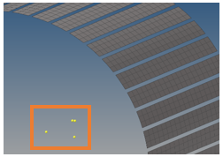
図 1. Temporary nodes in the model
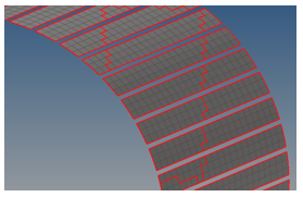
図 2. Elements not connected detected with the "free edges" tool in HyperMesh
HyperMesh graphic area manipulation
- To Translate the geometry: use Ctrl + right click
- To rotate the geometry: use Ctrl + left click
- To zoom in/out the geometry: use control + roll scroll wheel
- To manage the transparency / opacity of geometry or mesh, use the following
icons (below the graphic area):


- To manage the displaying of the model components geometry and mesh, use
:
HyperMesh entities selection
Some tips concerning entities selection (for first HyperMesh usage) are presented here:
- Click on surfs

Remarks:
 allows to
change the entity type to select.
allows to
change the entity type to select. allows to
reset the selected entities
allows to
reset the selected entities - Option 1: click on the yellow field to open the temporary extended menu to
get multiple selection methods. For example: « all / displayed / … »

- Option 2: select face by face on the graphic with the mouse left click
(without Ctrl button). The selected face is highlighted (in white). To
deselect a face, use the mouse right click
Mechanical mesh in HyperMesh
- Make sure to select the OptiStruct user profile when opening
HyperMesh:
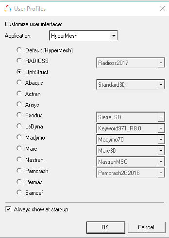
You can review this window by clicking on the
 icon.
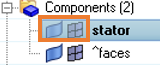
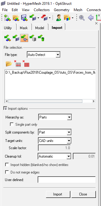
icon. - Import CAO file of the geometry to consider (stator / rotor / all / …). Here
we consider stator part:
- Menu :
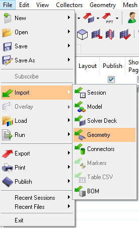
- Click on the following icon to select the CAO file
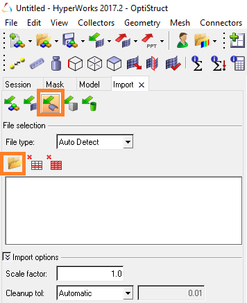
The path of the selected CAO file appears in the window below the icon
- Click on import to confirm the import
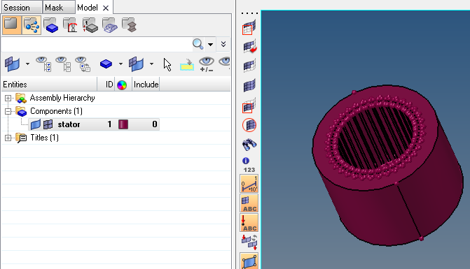
The geometry is imported and visible in the graphic area, and the Model tab contains the different geometry components
- Menu :
-
Mesh the solid components (volume mesh):
In our example case the volume mesh is the best tool to use.
This mesh step should be adapted according to the complexity of the input geometry.
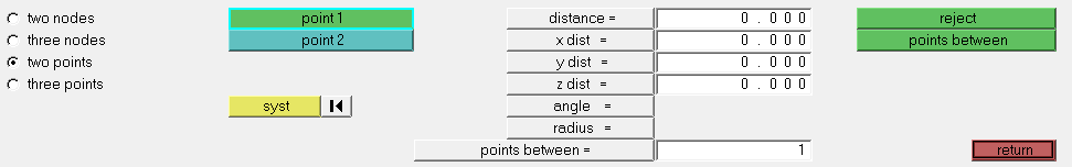
- Check the geometrical distance between two points to define the mesh
element size:
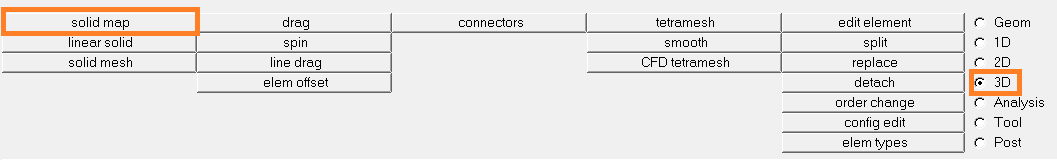
- Open the 3D panel and select the
solid map tool:
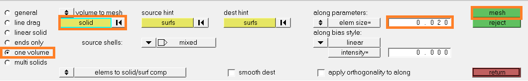
- To mesh, follow the steps below:
- Select one volume
- Click on solid (highlighted with blue line)
- Select the components to mesh on the graphic
- Fill the element size
- Click on mesh
- If the mesh is ok, click on return.
Otherwise, click on reject and modify
the mesh data.
- Check the geometrical distance between two points to define the mesh
element size:
- Create the faces of the solid component(s) containing the surface mesh
support:
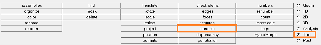
- Select the Tool panel and the tool
faces
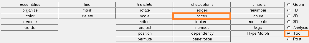
- To generate a component containing the external surface mesh:
- Click on comps
- select the component(s)
- click on find faces
 The component ^faces has been created. It contains the faces of all the solid component(s)
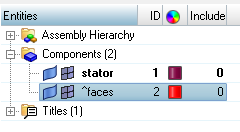
- Right click on this component and select isolate to display only the surface mesh
- Select the Tool panel and the tool
faces
- In the ^faces component, delete the surface mesh
which should not be exported. This step can be fastidious, so the selection
by relation and the reverse command can be used. On
this example:
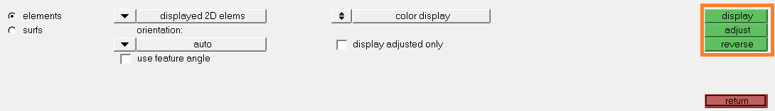
- Click on the following icon:

The following window is opened:
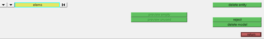
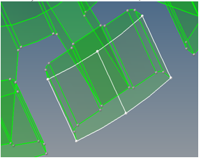
- Follow the below steps described:
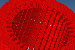
- Select one element by tooth as on the image
- Click twice on elems to activate the
extended menu. At the first click select by
face.
All the meshed teeth faces are selected
- At the second click on elems select
reverse
All the other meshed faces are selected
- Select one element by tooth as on the image
- Click on delete entityThe final face mesh corresponds to:
- Right click on ^faces component, rename and delete ^ to export it.
- Click on the following icon:
- (optional) Save the HyperMesh model :
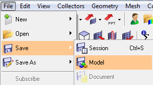
- Export the displayed mesh :
- Menu : :
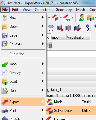
- Ensure to display only the meshed faces of the faces component
- Export the displayed mesh in Optistruct
format:
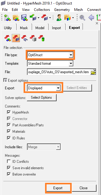
- Menu : :
Superimposed nodes problem
HyperMesh, contrary to Flux, allows the creation of superimposed nodes / elements. Consequently, sometimes the exported mesh can be duplicated and superimposed (often because of a user manipulation error, for example by clicking two times on mesh). In Flux, the support creation using this mesh fails.
In this paragraph, the method to merge superimposed nodes is presented.
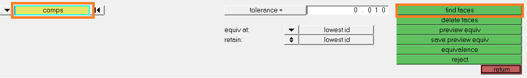
Attention: this command must be used carefully because some close points (under tolerance value) can be merged.- Open the HyperMesh meshed model
- Launch the command Equivalence on nodes :
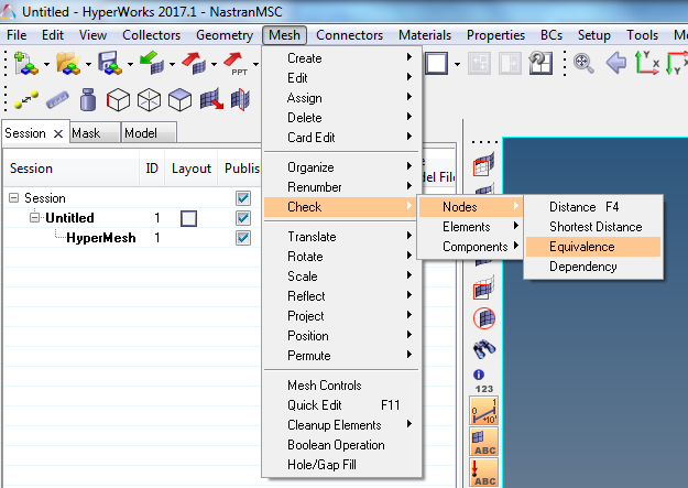 Following window opens :
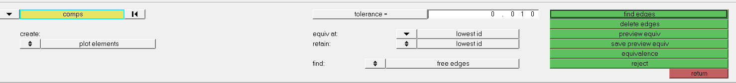
-
- Click on comps :

- Select faces and click on
select
- Click on comps :
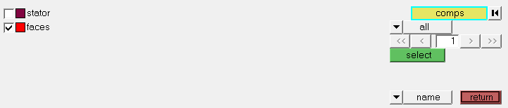
- Verify the tolerance value and click on preview equiv
.
This step helps you to review the nodes that HyperMesh detects within the tolerance.
If you agree click on equivalence.
If not modify the tolerance and repeat the above steps.
Then, click on return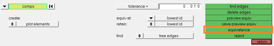
At the bottom left of HyperMesh window, the number of equivalenced nodes is indicated: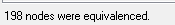
- Export the mesh by following the step 5 of the previous step/action table.
Free nodes problem
HyperMesh allows free nodes which are not attached to elements. If the mechanical mesh contains such nodes, the mesh import fails in Flux.
2 solutions in HyperMesh are proposed here.The first solution:
- Open the Geom panel below the graphic area and select the temp
nodes tool:
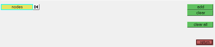
- Click on nodes and select all.
Click on clear all
- Export the mesh by following the step 5 of the previous step/action table
The second solution:
- On the window below the graphic area, select Analysis and
preserve node:
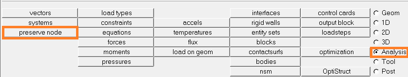
- Click on nodes and select all.
Click on clear all preserved.
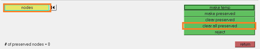
The preserved nodes will not be exported
- Export the mesh by following the step 5 of the previous step/action table.
It will be used to setup the NVH analysis.