Magnetic forces computation and export in Flux
Introduction
- Create the computation support
- Compute the forces and forces harmonics
- Visualize the forces
- Export the forces
Flux project
The Flux project can be in 2D or 3D in transient magnetic application (for NVH analysis).
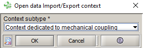
Import/Export context
The Import/Export context is dedicated to all couplings with other software, including the coupling with OptiStruct. In future, this context will replace all the specific coupling contexts including the mechanical analysis context.
To enter in the Import/Export context respectively after and before solving:
Mechanical context
When entering in the Import/Export context, user has to choose the dedicated context: Mechanical or thermal or generic.
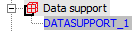
Creation of the support
In this part, the approach to create the support defined by importing a mesh is presented. The imported mesh corresponds to the mesh exported before which will be used for the forces computation in Flux and for the vibratory analysis in OptiStruct.
There is also in Flux a support defined by Flux entities, but this requires an interpolation step when importing forces into HyperMesh (for more information, please refer to the online help).
- Open the box to create the support:
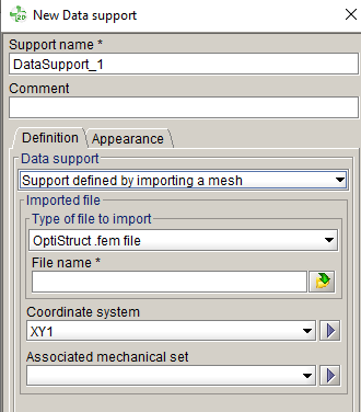
- Choose the data support Support defined by importing a mesh
- Choose the type of file to import OptiStruct .fem file
- Select the file to import
- Select the coordinate system. 注: Depending on the length units, user may have to create and select a new global coordinate system with the right units.
- Select the mechanical set.
It is especially useful if the support must follow a moving mechanical set.
- Click on OK to create the support.The data support is created:
Compute the forces
- Open the box to create the forces data collection:
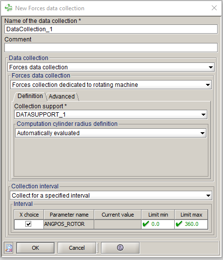
- Choose the Forces data collection Forces collection dedicated to rotating machine with mesh import
- Choose the data support created before
- Choose the automatic computation of the radius in the airgap.
The forces will be computed on this radius before being projected on the imported mesh.
A value can be setted by the user. In this case, it is advised to choose its value on ¼ distance of the airgap thickness, stator/rotor side, according to where the imported support is. - Choose the collection interval:
- Collect for all steps of the scenario
- Or collect for a specified interval. This choice allows reducing computation time
- Click on OK to create the data collectionThe data collection is created:
- Open the box to create a derived data collection:
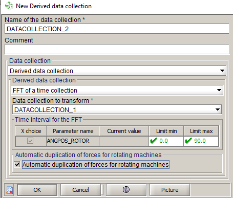
- Select the FFT of a time collection
- Select the data collection DATACOLLECTION_1 created before
- Select the time interval for the FFT, corresponding to one period.
- Select Automatic duplication of forces for rotating machines
- Click on OK to create the derived data
collection.The derived data collection is created:
- Evaluate the forces and forces harmonics values:注: if the project is not solved, this command will not be available. In fact, the collection is done during the solving (it allows reducing computation time).
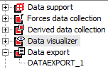
Visualize the forces
- Open the box to visualize the forces:
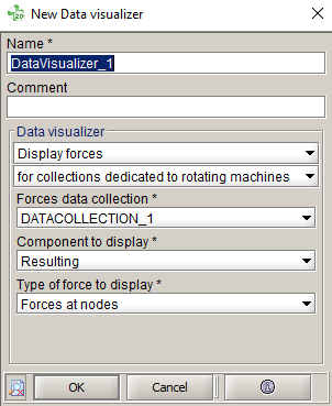
- User can choose display forces or display harmonic forces and user has to select for collections dedicated to rotating machines
- Choose the data collection to visualize (forces or forces harmonics)
- It is possible to visualize the following components of the forces
vectors:
- Resulting
- Normal
- Tangent
- It is possible to visualize:
- Forces at nodes
- Global forces. It corresponds to the resulting forces on one geometrical part (one stator teeth for example)
- If user has selected the forces harmonics visualization, the rank of the harmonic to visualize must be chosen.
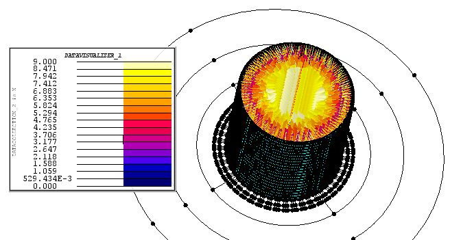
- Click on OK to create the data visualizer entity and
visualize the forces.The data visualizer is created and the forces arrows displayed:
- When the forces arrows are visible, it is possible to plot an evolutive
curve:
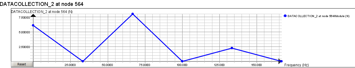
- Forces harmonics module depending on the frequency:
- Make the harmonics arrows visible
- Open the FFT data evolution curve:
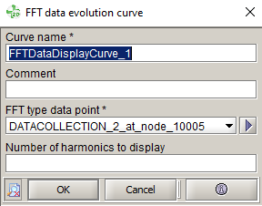
- Choose the node in the graphic (FFT type data point)
- Select the number of harmonics to display
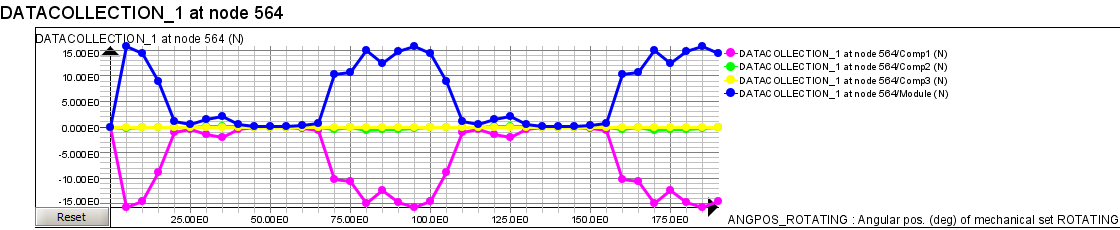
- Forces module depending on the time:
- Make the forces arrows visible
- Open the Standard data evolution curve
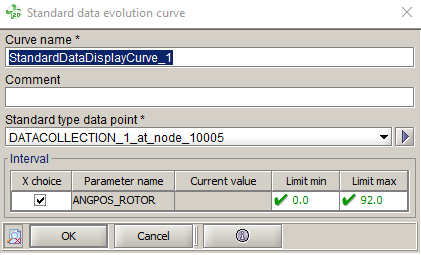
- Choose the node in the graphic (Standard type data point)
- Define the time/position interval
- Forces harmonics module depending on the frequency:
Export the forces
- Open the box to export the forces:
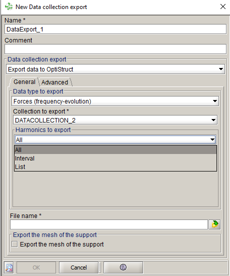
- Select the Forces (frequency-evolution) to export
- Select the derived data collection DATACOLLECTION_2 to export
- Select harmonics to export (the selection may be done by choosing either all, an interval or a list of harmonics).
- Choose the file name
- Click on OK to export the forces harmonics and create
the data export entity:
The data export entity is created and the forces harmonics exported in a .fem file: