RD-E: 0500 Beam Frame

A beam frame receives an impact from a mass having initial velocity.
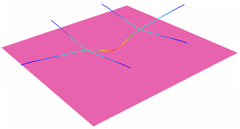
A beam frame with clamped extremities receives an impact at its mid-point from a pointed mass having initial velocity. The material is subjected to the elasto-plastic law of Johnson-Cook. The model is meshed with beam elements. An infinite rigid wall with only one secondary node, including the impacted node, is subjected to the initial velocity. This example is considered a dynamic problem and the explicit solver is used.

rad_ex_5_beam
Figure 1.

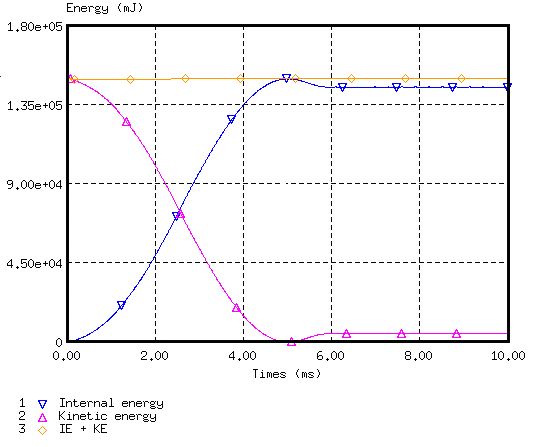
The explicit approach leads to finding a quasi-static equilibrium of the structure after impact.

Options and Keywords Used

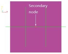
The impacting mass is simulated using a sliding rigid plane wall (/RWALL) having an initial velocity of 10 ms-1and a mass of 3000 g. Only one secondary node exists: the node O to simulate a point impact.
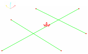
Points A, F, F', D, E and E' are fully fixed.

rad_ex_fig_5-3
Figure 2. Boundary Conditions

rad_ex_fig_5-4
Figure 3. Rigid Wall Type Infinite Plane

Input Files

Refer to Access the Model Files to download the required model file(s).

The model files used in this example include:

FRAME_*.rad

Model Description

The purpose of this example is to perform a static analysis using beam elements.
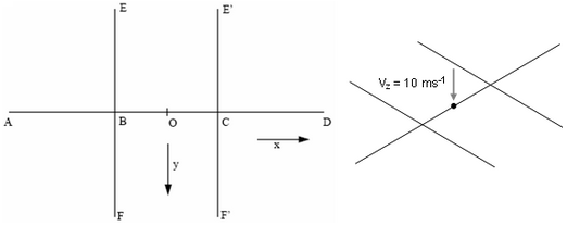
A pointed mass (3 kg) makes an impact at point O of a beam frame (see Figure 4 for the geometry) using a speed of 10 ms-1in the Z direction. The beams are made of steel and each beam section is square-shaped (each side being 6 mm long).

rad_ex_fig_5-1
Figure 4. Geometry of the Frame

Dimensions are: AB = BC = CD = BE = BF = E'C = CF' = 90 mm.

Points A, D, E, F, E', and F' are fixed.
Beam Properties
Cross section
36 mm2
Moments of inertia in Y and Z
108 mm4
Moments of inertia in X
216 mm4
The steel material used has the following properties:
Material Properties
Density
0.0078 [ g m m 3 ] MathType@MTEF@5@5@+= feaagKart1ev2aaatCvAUfeBSjuyZL2yd9gzLbvyNv2CaerbuLwBLn hiov2DGi1BTfMBaeXatLxBI9gBaerbd9wDYLwzYbItLDharqqtubsr 4rNCHbGeaGqiVu0Je9sqqrpepC0xbbL8F4rqqrFfpeea0xe9Lq=Jc9 vqaqpepm0xbba9pwe9Q8fs0=yqaqpepae9pg0FirpepeKkFr0xfr=x fr=xb9adbaqaaeGaciGaaiaabeqaamaabaabaaGcbaWaamWaaeaada WcaaqaaiaadEgaaeaacaWGTbGaamyBamaaCaaaleqabaGaaG4maaaa aaaakiaawUfacaGLDbaaaaa@3BBC@
Young's modulus
200 000 [ MPa ] MathType@MTEF@5@5@+= feaagKart1ev2aqatCvAUfeBSjuyZL2yd9gzLbvyNv2CaerbuLwBLn hiov2DGi1BTfMBaeXatLxBI9gBaerbd9wDYLwzYbItLDharqqtubsr 4rNCHbGeaGqiVu0Je9sqqrpepC0xbbL8F4rqGqFfpeea0xe9vq=Jb9 vqpeea0xd9q8qiYRWxGi6xij=hbba9q8aq0=yq=He9q8qiLsFr0=vr 0=vr0db8meaabaqaciGacaGaaeqabaWaaeaaeaaakeaadaWadaqaai Gac2eacaGGqbGaaiyyaaGaay5waiaaw2faaaaa@3BE6@
Poisson's ratio
0.3
Yield stress
320 [ MPa ] MathType@MTEF@5@5@+= feaagKart1ev2aqatCvAUfeBSjuyZL2yd9gzLbvyNv2CaerbuLwBLn hiov2DGi1BTfMBaeXatLxBI9gBaerbd9wDYLwzYbItLDharqqtubsr 4rNCHbGeaGqiVu0Je9sqqrpepC0xbbL8F4rqGqFfpeea0xe9vq=Jb9 vqpeea0xd9q8qiYRWxGi6xij=hbba9q8aq0=yq=He9q8qiLsFr0=vr 0=vr0db8meaabaqaciGacaGaaeqabaWaaeaaeaaakeaadaWadaqaai Gac2eacaGGqbGaaiyyaaGaay5waiaaw2faaaaa@3BE6@
Hardening parameter
134.65 [ MPa ] MathType@MTEF@5@5@+= feaagKart1ev2aqatCvAUfeBSjuyZL2yd9gzLbvyNv2CaerbuLwBLn hiov2DGi1BTfMBaeXatLxBI9gBaerbd9wDYLwzYbItLDharqqtubsr 4rNCHbGeaGqiVu0Je9sqqrpepC0xbbL8F4rqGqFfpeea0xe9vq=Jb9 vqpeea0xd9q8qiYRWxGi6xij=hbba9q8aq0=yq=He9q8qiLsFr0=vr 0=vr0db8meaabaqaciGacaGaaeqabaWaaeaaeaaakeaadaWadaqaai Gac2eacaGGqbGaaiyyaaGaay5waiaaw2faaaaa@3BE6@
Hardening exponent
1.0

All other coefficients are set to default values. Plasticity is taken into account using LAW2 without failure.

Model Method
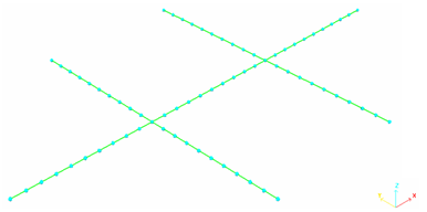
The mesh is a regular beam mesh, each beam being 9 mm long (total = 70 beams).

rad_ex_fig_5-2
Figure 5. Mesh of the Frame Showing the Position of the Nodes

Results

Curves and Animations
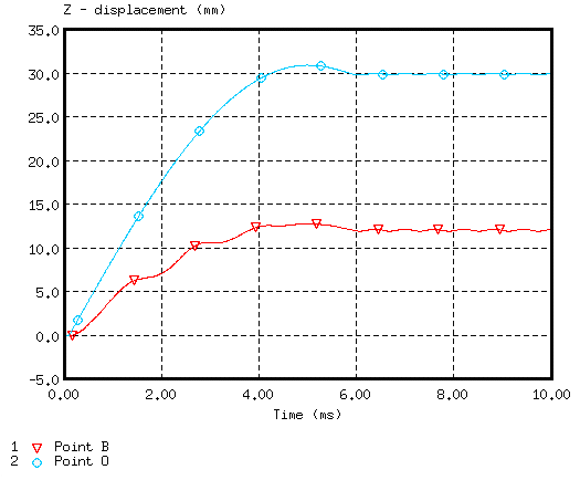
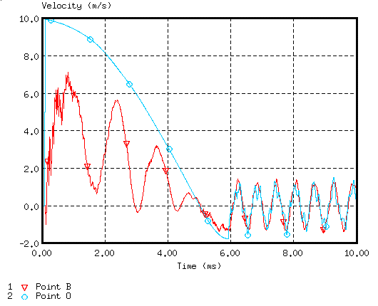
The main results refer to the time history of points B and O with regard to displacements and velocities.

rad_ex_fig_5-5
Figure 6. Displacements of Points B and O
rad_ex_fig_5-6
Figure 7. Velocity of Points B and O (stabilization)
rad_ex_fig_5-7
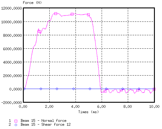
Figure 8. Normal and Shear Force on Beam Element 15 (near to point O)
rad_ex_fig_5-8
Figure 9. Energy Assessment (stability reached at in 6 ms)
rad_ex_fig_5-9
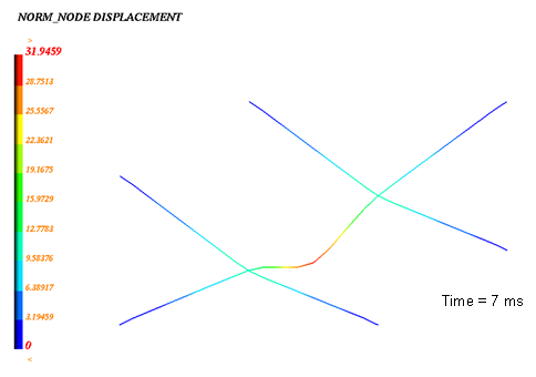
Figure 10. Node Displacement (max. = 30.96 mm)
rad_ex_fig_5-10
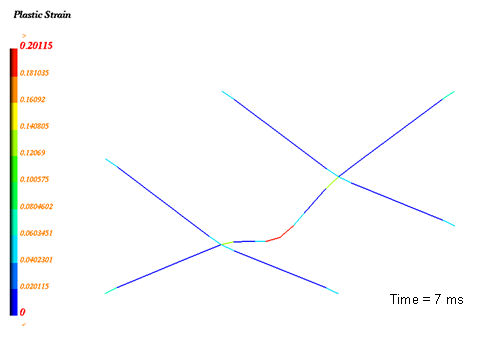
Figure 11. Plastic Strain (max. = 20.1%)