/FAIL/SNCONNECT
Block Format Keyword Describes the failure model for CONNECTION material with plastic displacement criteria. This model allows a different failure behavior in normal and shear directions.
Format
| (1) | (2) | (3) | (4) | (5) | (6) | (7) | (8) | (9) | (10) |
|---|---|---|---|---|---|---|---|---|---|
| /FAIL/SNCONNECT/mat_ID/unit_ID | |||||||||
| Ifail_so | ISYM | ||||||||
| fct_ID0N | fct_ID0S | fct_IDFN | fct_IDFS | XSCALE_0 | XSCALE_F | AREAscale | |||
| (1) | (2) | (3) | (4) | (5) | (6) | (7) | (8) | (9) | (10) |
|---|---|---|---|---|---|---|---|---|---|
| fail_ID |
Definitions
| Field | Contents | SI Unit Example |
|---|---|---|
| mat_ID | Material identifier. (Integer, maximum 10 digits) |
|
| unit_ID | Unit Identifier. (Integer, maximum 10 digits) |
|
| Parameter for the beginning of
damage, due to moment loads. 2 (Real) |
||
| Exponent for the beginning of damage,
due to combined shear and normal loads. 2 (Real) |
||
| Parameter for the final damage failure,
due to moment loads. 2 (Real) |
||
| Exponent for the final damage failure,
due to combined shear and normal loads. 2 (Real) |
||
| Ifail_so | Solid failure flag.
(Integer) |
|
| ISYM | Rupture deactivation flag for compression.
(Integer) |
|
| fct_ID0N | Function identifier defining a scale
factor for displacement rate dependency in normal direction in initial yield
function. Default = 0 (Integer) |
|
| fct_ID0S | Function identifier defining a scale
factor for displacement rate dependency in tangential direction in initial yield
function. Default = 0 (Integer) |
|
| fct_IDFN | Function identifier defining a scale
factor for displacement rate dependency in normal direction in rupture yield
function. Default = 0 (Integer) |
|
| fct_IDFS | Function identifier defining a scale
factor for displacement rate dependency in tangential direction in rupture yield
function. Default = 0 (Integer) |
|
| XSCALE_0 | Scale factor for the abscissa
displacement rate for initial function. Default = 1.0 (Real) |
|
| XSCALE_F | Scale factor for the abscissa
displacement rate for rupture function. Default = 1.0 (Real) |
|
| AREAscale | Failure scale factor for area
increase. 5 Default = 0.0, this option is not used (Real) |
|
| fail_ID | Failure
criteria identifier. 3 (Integer, maximum 10 digits) |
Example (Connect)
#RADIOSS STARTER
#---1----|----2----|----3----|----4----|----5----|----6----|----7----|----8----|----9----|---10----|
/UNIT/1
unit for mat
                  kg                  mm                  ms
#---1----|----2----|----3----|----4----|----5----|----6----|----7----|----8----|----9----|---10----|
#-  2. MATERIALS:
#---1----|----2----|----3----|----4----|----5----|----6----|----7----|----8----|----9----|---10----|
/MAT/LAW83/1/1
CONNECT MATERIAL
#              RHO_I
              7.8E-6
#                  E                         Imass
                  20                             0
#  Fct_ID1                      Y_scale1            X_scale1               ALPHA                BETA
       200                             1                   1                   0                   2
#                 RN                  RS   Fsmooth                Fcut
                  .2                  .4         0                   0
#  Fct_IDN   Fct_IDS              XSCALE
         0         0                   0
/FAIL/SNCONNECT/1/1
#            ALPHA_0              BETA_0             ALPHA_F              BETA_F  Ifail_so      ISYM
                   0                   2                   0                   2         1         1
#   Fct_0N    Fct_0S    Fct_FN    Fct_FS            XSCALE_0            XSCALE_F           AREAscale
      2001      2002      2003      2004                   1                   1                   0
#---1----|----2----|----3----|----4----|----5----|----6----|----7----|----8----|----9----|---10----|
#-  3. FUNCTIONS:
#---1----|----2----|----3----|----4----|----5----|----6----|----7----|----8----|----9----|---10----|
/FUNCT/200
MAT83 curve
#                  X                   Y
                   0                   1
                   1                   1
#---1----|----2----|----3----|----4----|----5----|----6----|----7----|----8----|----9----|---10----|
/FUNCT/2001
Fct_0N
#                  X                   Y
                   0                  .5
                   1                  .5
#---1----|----2----|----3----|----4----|----5----|----6----|----7----|----8----|----9----|---10----|
/FUNCT/2002
Fct_0S
#                  X                   Y
                   0                  .5
                   1                  .5
#---1----|----2----|----3----|----4----|----5----|----6----|----7----|----8----|----9----|---10----|
/FUNCT/2003
Fct_fN
#                  X                   Y
                   0                   1
                   1                   1
#---1----|----2----|----3----|----4----|----5----|----6----|----7----|----8----|----9----|---10----|
/FUNCT/2004
Fct_fS
#                  X                   Y
                   0                   1
                   1                   1
#---1----|----2----|----3----|----4----|----5----|----6----|----7----|----8----|----9----|---10----|
#ENDDATA
/END
#---1----|----2----|----3----|----4----|----5----|----6----|----7----|----8----|----9----|---10----|
Comments
- This failure model is compatible only with the connection materials, /MAT/LAW59 (CONNECT) and /MAT/LAW83. The connection materials are independent of height, so failure is based on displacement, instead of strain.
- A combined energy failure criteria is
defined as:
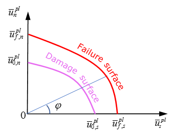
Figure 1.Where, and are the plastic displacement in the normal and tangential directions.
Damage of element begins when the damage surface is reached which is described by:(1) Where, and are the function of fct_ID0N and fct_ID0S. If there are no rate effects, the curves will be constant.
The damage factor is computed as:(2) And the stress is reduced as:(3) The element is deleted when the rupture surface is reached:(4) Where, and are the function of fct_IDFN and fct_IDFS. If there are no rate effects, the curves will be constant.
-
.Where, is the angle between the normal of the lower surface and the normal of the upper surface of the solid element.
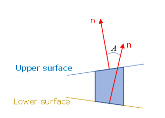
Figure 2. - Parameters are the scale factors used to describe the moment effect (for example, in a peeling test) for damage initiation and failure.
- Parameters
are fitted using a test which combines normal and shear
loards (30° test, 45° test or 60° test, etc.). At least one combined test is needed to
fit the parameters
. Figure 3 and Figure 4
show the effect of
on damage initiation and failure in combined test.
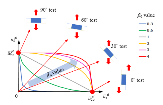
Figure 3. Displacement at damage initiation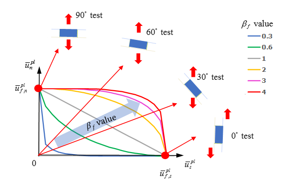
Figure 4. Displacement at failure
-
.
- The fail_ID is used with /STATE/BRICK/FAIL and /INIBRI/FAIL. There is no default value. If the line is blank, no value will be output for failure model variables in the /INIBRI/FAIL (written in .sta file with /STATE/BRICK/FAIL option).
- With /ANIM/BRICK/VDAMi following damage variable value could be output in
an animation file:
VDAM1 = d is the damage value, which ranges from [0, 1].
VDAM2 = the damage surface output, which ranges from [0, 1].
VDAM3 = the rupture surface output, which ranges from [0, 1].
- The area is calculated as the mean value of the upper and lower surface of the solid element. If the actual area reaches the value of initial area multiplied by the AREAscale factor, the whole element will be deleted. The default value is set to zero. This causes no deletion, due to area increase. The application is to prevent shooting nodes, if the cohesive element nodes will be released, when surrounding elements start to fail and erode.