Altair HyperMesh 2022.1 Release Notes
Aeroelasticity
Resolved Issues
- The Aeroelasticity Browser no longer shows empty folders.
- Flutter curves were not working for OptiStruct input files on Linux. This has been fixed.
- The Move tool now shows location info in local coordinate systems.
API
- HyperWorks Context APIs
- A new set of Tcl API commands has been added to allow you to programmatically interact with HyperWorks contexts. The list of commands can be found in the Context Commands section of the HyperWorks Reference Guide.
- HyperMesh Panel APIs
- The HyperMesh panels are being gradually phased out with the complete removal scheduled for the v2023 release. More than 400 individual panels and subpanels have been already removed in HyperWorks v2022.1. The panel API commands will be also deprecated and removed with the v2023 release. They remain supported until then. However, referencing a deprecated panel in these commands will result in a silent failure. For more details and the full list of new features and enhancements, see the 2022.1 API Programmer’s Guide section of the HyperMesh Reference Guide.
Browsers
Enhancements
- Browser population with selected content
- Working with selected contents in browsers is now supported. You can
pick the required entities, including Nodes and Elements, to be shown in
respective browser and further review and edit data with attribute
columns.

Figure 1. - Attribute Column support for list selectors
- All list selectors including Main and Secondary fields of a contact can
now be added as columns in browser for bulk review and editing of
data.

Figure 2. - Filtering support in ID manager
- Search and filtering with Auto complete, Columns filters, and Predefined
filters, is now supported in the ID manager.

Figure 3. - Massive performance improvements
- Performance improvement (60-80%) in invoking context menus in the Model Browser.
- Embedded Entity Editor in Ansys interface
- Embedded Entity Editor is now supported in the Ansys interface for quick review and editing of referenced entity attributes.
- Context menu reorder
- Context menus have been reordered to have a consistent order of menus across entities, folders, and browsers.
- API to control browser updates
- Public API hm_blockbrowserupdate <0/1> has been added to control browser updates while running scripts.
Resolved Issues
- Performance issue while showing data in the Entity Editor for load steps with multiple references.
- Collected entities were not updated correctly upon making the respective collectors inactive.
- Idle selector would switch to all previously accessed entities during model load.
- Review of collected entities was not dynamic.
- Elements and Geometry visibility icons would fail to update when browser is filtered with string values.
- Filtering of Part representation column with <Empty> would not work.
Known Issues
- Entity Editor is not cleared when entity is removed from filtered browser list.
Certification
Enhancements
- Generic Structural Element
- It is now possible to directly select Components, Sets, or Parts while
creating generic structural elements. Only Sets of elements are
supported. On Run, the method is evaluated on elements from
Components/Parts/Sets.
- Split option "none" or "by entity" generates a single structural element or one per entity selected.
- DesignpointMethod Evaluation System
- The system used to extract result information is no longer set at the
Designpoint Set level but at each method level. It is also possible to
define a user system for result extraction. If a defined extraction
system is not compatible with data query, then the Global system is used
instead.
The System option is removed from the Run tool while running on elements since it is controlled per method.
- Built-in method JointLoad
-
- Method arguments are reworked as datanames instead of metadata.
Options now have tooltips to describe option behavior.
- Legacy files will be updated if method is Run to use new style arguments.
- New argument "Extraction" is added to control output:
- All - outputs all debug info (same as 2022) leading to 85 columns in table.
- Forces and Fluxes - outputs fastener forces as well as far field fluxes (Nxx/Nyy..) but without all debug info leading to less columns.
- Fastener Force - outputs only fastener forces Fx,Fy,Fz and max tension.
- Method arguments are reworked as datanames instead of metadata.
Options now have tooltips to describe option behavior.
-
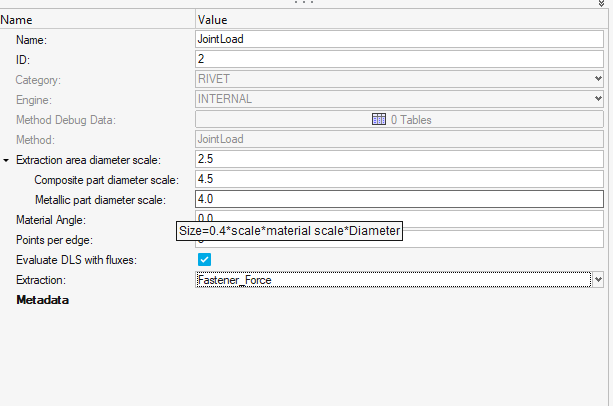
Figure 4. - Built-in attributes mapping for OS H3D files
-
- Added support of native H3D files when mapping function arguments with result data.
- 1D Forces & 1D Moments as well as Stress are correctly mapped and no more need user attributes defined in library.
Resolved Issues
- Built-in method JointLoad
-
- Chaining a method after JointLoad was broken in version 2022.0
and is solved in 2022.1.
- As a result, the JointLoad table has an extra column added for entityid.
- Box Angle (renamed as Material Angle) used to only rotate the extraction box but was still extracting forces and fluxes in pierced shell material system. It now properly query components in rotated system.
- Chaining a method after JointLoad was broken in version 2022.0
and is solved in 2022.1.
Composites
New Features
- Injection Molding Ribbon
- The injection molding ribbon facilitates the development of accurate structural simulation models for reinforced injection molded parts and assemblies. It is used to map fiber orientation tensors from a molding simulation to a structural model which can then be solved using Multiscale Designer.
-
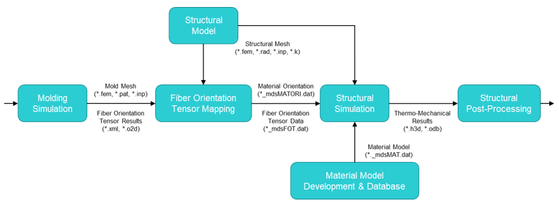
Figure 5. Injection Molding – Structural Simulation Workflow - Ply Rename Dialog
- Several automated ply renaming methods are available:
-
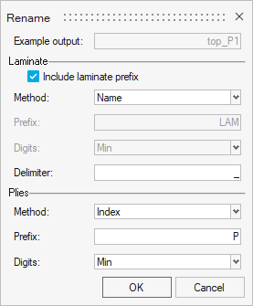
Figure 6. - Composite Stress Toolbox
-
- Support for element selection on all laminate analyses.
- Supported solvers:
- OptiStruct: PCOMP(G), PCOMPP
- Nastran: PCOMP(G)
- Abaqus: SHELLSECTION_COMPOSITE
- All values are calculated assuming mid-plane laminates; hence offsets in properties are disregarded.
- Supported solvers:
- Thermal support:
- Thermal properties for materials, plies, zones,
laminates and elements.
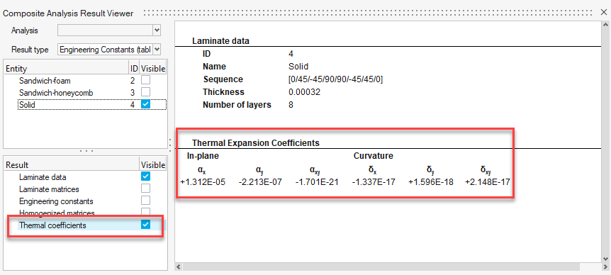
Figure 7. - Extension of Composite Plate Loads to include
temperature change at laminate top and bottom.
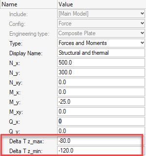
Figure 8. - Load response including combined thermal and mechanical
loads.

Figure 9. - Multiscale Designer material models supported for engineering constants and load response analyses.
- Thermal properties for materials, plies, zones,
laminates and elements.
- Support for element selection on all laminate analyses.
Enhancements
- General
-
- Absorb Properties dialog moved from Aerospace pull-down to Composite Browser context menu.
- Default materials in Composite Browser updated for OptiStruct (MAT9OR), Nastran (MAT9ORT), and Abaqus (TYPE=Engineeering Constants).
- API to export material reference orientations to csv.
- Composite Stress Toolbox
-
- Restructured result tree for load response / failure analysis for quicker access to the desired results.
- Card image added to material engineering constants.
- Improved warning and error messaging for missing material properties.
- Performance improvements for analyses with many entities selected.
- Results are directly available as TCL dictionary. File based results are optional.
- MAT1 in OptiStruct and Nastran only requires 2 properties out of E, G and Poisson's ratio. The missing third is calculated for user convenience.
Resolved Issues
- General
-
- Performance improvement for Wound and Unidirectional Weave ply types on import, orientation visualization, thickness visualization, and mass calculation
- Ply layers visualization for Wound ply type
- Composite Browser performance with many laminates
- PCOMP/PCOMPG offset in detailed 3D visualization
- Material Reference Orientation tool can be run multiple times if output is system entities.
- Corruption of unrelated properties and element sets during composite property absorption
- Composite Browser zones don't have ply list
- Composite Stress Toolbox
-
- Missing scrollbar after resizing the result viewer
Known Issues
- General
-
- Slow performance in Composite Browser when many plies present in laminate (workaround is to place ply without shape in laminate while editing)
- Absorb properties in Ansys profile updated for direct property assignment
- Import of Catia Stack-up file
- Instance ply editing forces pop-up for datanames which should not require conversion to main ply
- Laminate export to spreadsheet if one or more plies missing material assignment
- Composite Stress Toolbox
-
- Element based analyses for ply-based properties do not consider draping data of the element, but the nominal layup definition. Realize the laminate, if needed, to get access to the draped laminate properties.
- Limitation: Composite Plate Load strain is handled as initial strain when combined with thermal load. Option to use strains as boundary conditions is not yet available.
- Limitation: Temperature-profile through laminate thickness is assumed to be linear. Potentially different thermal conductivity of materials is not considered.
Connectors
New Features
- Supported Solvers
- Connectors are now supported in Feko and EXODUS solver profiles.
- Aerospace Realizations
-
- Huth and User Defined Huth have been added as a method type to
the following realizations:
- OptiStruct and Nastran:
- Rbe3_cbusg_reb3
- Cfast_elem
- Cfast_prop
- Abaqus:
- Fastener_non_coincident
- OptiStruct and Nastran:
- The Method Type allows you to specify:
- Diameter
- Material (from the model, the Young's modulus, or from a file)
- Connection Type (Rivet, and Bolt)
- K4,K5 and K6 (Defaults set to 100, 100000000, 100000000)
- a, b1 and b1 (when set to user defined)
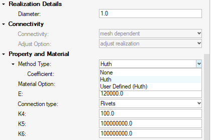
Figure 10.
- Single and Double shear calculations are handled automatically.
- These defaults can be saved within the Control Manager, allowing you to define their fixing control once and reuse.
- A new attachment type has been added to replace the Stuck Node
tool.

Figure 11.
- Huth and User Defined Huth have been added as a method type to
the following realizations:
- Solids from Connectors
-
- Solids are now selectable in the Point, Line, and Fastener tools.
- For Line connectors, the Midline Extraction process creates a Connector at the midline.
- Metadata extraction now has Partial or Exact Name Matching for Link Metadata Name.
- Custom metadata mapping can be defined in the Connector Preferences area. This allows you to define any metadata on a part that would be mapped to the Connector as metadata.
- Post Script Removal
-
- Contacts can now be created from within the feconfig definition. The keyword contact can be added to the *head definition.
- Automatically created properties and materials are assigned to the connector during realization.
- Systems and Vectors are automatically assigned to the realization.
- Minimum hole size is passed as the property diameter value when realizing Bar/Beam Fasteners.
- Diameter values can now be populated for all Rod/Bar/Beam/Fastener realizations directly (except Fasteners as per the previous point).
- The realization organization method can be changed within the control from: Single (per include), Linked Pair (Per link pairing), and Per Connector.
- "Collector Name Prefix" now populates the Property and Material names with the value.
- Absorbing Connectors will no longer point to the post scripts but the default values for the Connector types.
- The following realizations have been removed:
- Radioss:
- Weld: (Obsolete)
- Rod: (Obsolete)
- Bar2: (Not Used)
- LS-DYNA:
- Rod (Not Used)
- Radioss:
- The following realizations have had their post scripts set to
No/Skip when created through Controls as they are no longer
required:
- Spot Types:
- sealing
- fastener
- fastener-nodes
- Mastic
- acm (shell gap + coating)
- HC glue
- HC glue structural adhesive
- HC hexa spotweld
- HC welding line
- mat100 (hexa)
- HC beam spotweld
- mat100
- HC hemming
- mat196
- cweld (general)
- cfast_elem (GS)
- cfast_elem (GA-GB)
- cfast_prop (GA-GB)
- cfast_prop (GS)
- HiLock
- CGAP(G)
- acm (shell gap contact + coating)
- HC hexa spotweld
- type2 (spring)
- Line Types:
- hexa (adhesive-contact)
- adhesives (contact)
- hexa (adhesive-contact)
- mat196 (single row)
- hexa (adhesive-contact)
- type2(spring single row)
- type2(spring multiple row)
- Bolt Types:
- bolt (washer 1) BEAM44
- bolt (BEAM44)
- HC cylinder rigid
- HC spring bolt
- hinge
- bolt (general)
- bolt (cylinder rigid)
- bolt (cylinder spring)
- bolt (spider)
- bolt (washer 2) LINK10
- bolt (washer 1 alt) LINK10
- bolt (washer 1) LINK10
- bolt (LINK10)
- HC cylinder spring bolt
- HC cylinder rigid bolt
- Beam Clip
- bolt (CBAR)
- Area Types:
- adhesive (shell gap)
- adhesives (contact)
- type2 (adhesive-spring)
- Spot Types:
Enhancements
- Absorb Enhancements
-
- Custom configurations can be absorbed according to the configuration in the feconfig.cfg file.
- Cylinder Bolts can now be absorbed through Fastener Absorption.
- 1D absorption has been added to Lines and Areas. These are only for mesh dependent realizations.
- Absorption can now be performed ignoring the links to allow for a spotline over many comps to be combined.
- Absorption can now absorb group links.
- HyperWorks Enhancements
-
- The Connector Preferences are now remembered between sessions.
- The text in the hamburger menu options in the contexts have been updated for clarity.
- More link types (Nodes, Elements, Tags and Surfaces) have been added to the microdialog link tool.
- Selecting a Control when exiting the Control Manager now pushes the selected control to the tool.
- Trimming Area connectors has now been added to the micro during edit.
- Trimming Line connectors now keeps the sharp corners during trimming.
- General Enhancements
-
- Line connectors now have the ability to interchange ends.
- Automatically group link option added for Spots and Lines when the number of links is set to 2.
- Penta (mig) now has the option to explicitly dictate the connection type for Solid Edges where there are multiple valid configurations.
- Part Enhancements
-
- Change rule to "use uid" on link realization for part links added through automatic (proximity rule) during connector creation.
- Instance Sync will now bring Connector Groups through, allowing you to create a single connector at a Part Occurrence and instance Connectors throughout the model.
- Auto-reorganize has the option to create a Connector group for the Geometric Part. This allows the Connector to be placed back into the Part Hierarchy in the correct location.
- Attachments Enhancements
-
- Rigid Patch Attachments in LS-DYNA can have Properties and Materials defined.
- Absorbing a rigid patch populates the interface type.
- Rigid Spider Attachments in Radioss have a free node as the interface.
- The Connect Attachment workflow has no cap to the number of links. Previously this was set to 5.
- Rigid patches material attributes (Rho, E) are automatically assigned from the base material.
- The interface ID and Name is added as a column in the Connector Browser for Attachments.
- Attachments are created when Fastener creates a hole during realization with the option to create attachments.
- Node Attachments are organized into the Part to which the node belongs.
- Collinearity has been updated to work with Projection Attachments.
- Attachment links created using "Create Attachments from existing connectors" use "use name" rule when created.
- Seam Quad LTB Enhancements
-
- New cases have been added to facilitate different realization
shapes.
Figure 12. - The option has been added to allow tria elements in welds and the Heat Affected Zone has been added.
- Edge Snapping options have been changed from a specific number of elements to a search tolerance based on average element size or a specific input value.
- Use extension option added to allow the projection to consider
the continuation of the part to base the calculations from.
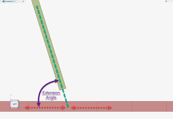
Figure 13.
- New cases have been added to facilitate different realization
shapes.
Resolved Issues
- Changing Attachment types keeps the interface ID.
- Custom postscripts are being correctly set within the controls.
- For xMCF, the PID is exported to the FEMDATA block.
- Hexa and Rod (spot/seam/area) tie are defined as sets rather than groups.
- Exporting Connectors with metadata was missing the comment $$.
- Local attribute to the connectors was overwritten after 2nd control change, this has been corrected.
- Cylinder bolts considers a single part as a whole rather than a series of components.
- FEMFAT Spot was missing the vector for the bar.
- Rigidlink (midnode) creates correctly for >2 links.
- Multiple head elements in the realization were being incorrectly organized. This has been corrected.
- The performance delay due to Considering Parts with Empty components during Link Detection of Connectors has been fixed.
- Performance during realization has been profiled and improvements have been delivered generically to improve performance.
- Diameter mapping file works for FEMFAT.
Design Explorer
New Features
- Field prediction reports can now train and view real-time predictions for
many more simulation results types.
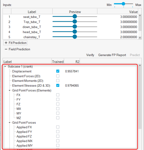
Figure 14.
Enhancements
- Explorations can now be evaluated with a single click by clicking
Run in the Evaluate dialog. An initial Export is
no longer required.
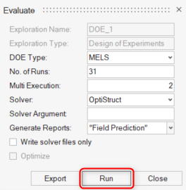
Figure 15. - Abaqus users can now access the Design Explorer ribbon.
- Accessing Tutorial Model Files
- You can now click a link, within a tutorial, to download the required model file(s) for that tutorial.
Resolved Issues
- Exploration runs fail using Radioss 2022 solver interface.
- Parameters can be multi-selected when creating design variables.
- Verification runs now working when frequency responses present.
Design Space
New Features
- Envelope creates a profile of a body that has undergone some form of transformation or movement and is a key tool for creating non-design primitives so that design space can be created appropriately.
Enhancements
- Accessing Tutorial Model Files
- You can now click a link, within a tutorial, to download the required model file(s) for that tutorial.
Extensions
New Features
The Extensions infrastructure providing the main entry point for custom content has been significantly enhanced:
- New Design of the Extension Manager
- Common appearance across applications
- Detailed view with more information (Location Path, Help Link)
- Multi-client Support
- Extensions can be developed for any HyperWorks client
- Support of custom toolbars
- Context Tcl API Commands
- Enter/exit and interact with a tool programmatically.
- The list of new commands can be found in the Context Commands section.

Figure 16.
Enhancements
The improvements to the Extension Manager include:
- Support of minimum product version
- Deleted extensions are removed from the extension manager instantaneously
Known Issues
- Complete unloading of all GUI Elements like ribbon pages and loaded libraries/procedures requires an application restart.
- Toolbars loaded with extensions are not exposed in the View – Toolbars menu.
Resolved Issues
- No more warning messages during deletion of extensions are shown.
General
New Features
- Dark Theme
- A new dark theme has been added for all HyperWorks products. It can be selected in application preferences.
-
Figure 17. - Beamsection Elastic
-
- New configuration for beamsection entity : Elastic
- Multi-material engine with contact
- Can use reference to sketch entity
- Properties lively updated with sketch update
- 3D visualization from sketch
-
Figure 18.
- Systems Tool
- A new systems tool is now available under the Model ribbon for all the solver profiles. The new workflow makes use of a interactive graphical manipulator to create and modify coordinate systems. You can manually drag the manipulator handles to the desired location or hold the Ctrl key and pick the necessary locations to quickly define the system orientation. In addition to a modern UI and workflow, the new tool provides features such as automatic system type conversion, one click orientation of the system about a principal axis, definition by entering coordinates, interactive translation/rotation of system along/around an axis.
-

Figure 19. - Select By Plane
- A new advanced selection method By Plane is now available for nodes, elements, components, points, lines, surfaces, solids, and loads. It allows selecting entities within a plane of a specified width, or within a cylinder normal to the plane with a specified radius. The plane is defined using the standard Vector tool manipulator.
-
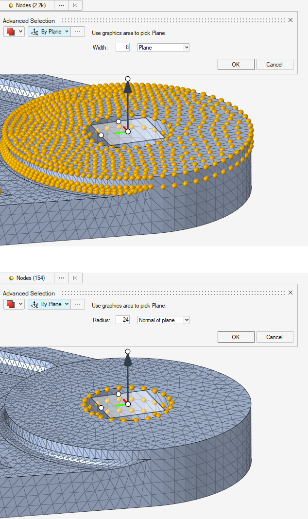
Figure 20. - New nodes while selecting
- While selecting nodes inside a tool, you can now add new nodes using snaps by activating the option in the right-click menu. New nodes added this way are automatically appended to your selection. Holding Shift to deselect them will also automatically remove them.
- True View
- The True View tool is now available in the View Toolbar and in the View Cube right-click menu. This new tool allows setting the camera view using model snaps and a rotator.
-
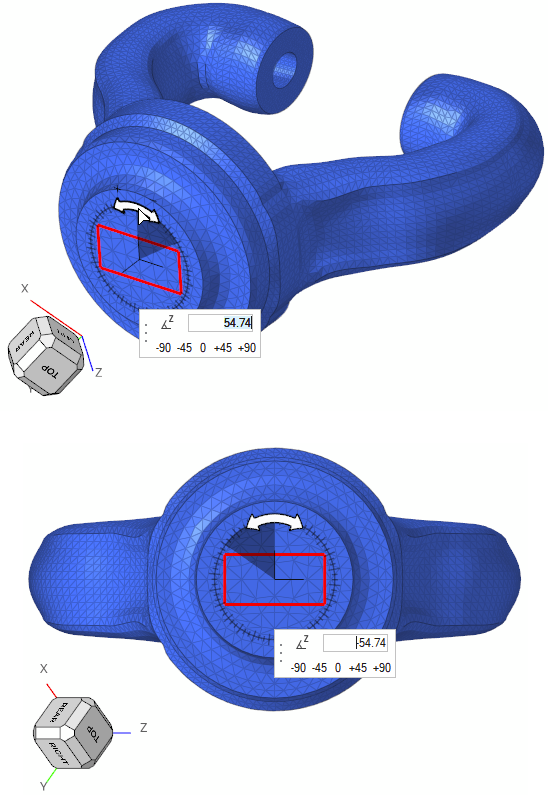
Figure 21.
Enhancements
- Showing/Clearing IDs
- Showing IDs now appends when you press the 'Q' keyboard shortcut in the graphics.
- If there is no selection it will clear all IDs.
- Show/Clear IDs has been added to the context menu.
- Organize
- The organize guide bar has been simplified so only valid entity types for destination are displayed based on your source.
- Source only displays entity types in the current model.
- Parts can be organized into part sets.
- Nodes and elements can be organized into sets.
- New sets can be created from the context menu in the Organize or idle tools.
- Graphical Background Color API
- The background color of the graphics area can be temporarily changed with a new API ::hwf::setbackgroundcolor #hexcolor. It can be added to a .tcl file and assigned to a keyboard shortcut to easily change the background color across HW products. This color won't be saved across sessions and won't change any text colors like changing the product theme color would.
- Performance of topology faces and edges selection has been improved in many scenarios.
- The modifier in the right-click menu has been renamed to .
- The Entity Selector keyboard shortcut ‘S’ is now also available for Sets.
- A new plane manipulator is now available in some tools, allowing translating
and rotating planes directly even without invoking the full Vector tool.
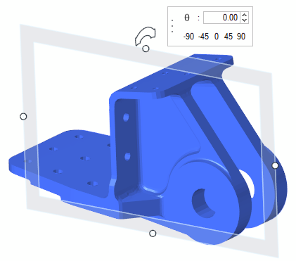
Figure 22. - Individual segments inside a Set Segment are now selectable directly using
the new entity type Segments.
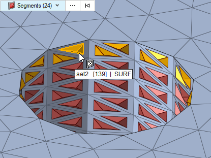
Figure 23. - A new Get/Set Angles option has been added to the View Cube right-click menu, which allows reviewing and editing camera view angle values.
Resolved Issues
- Export option that was added for HyperMesh component comments to preserve
the integrity of solver deck with previous releases is now available for
Include export. This option is added for Nastran and OptiStruct solver
profiles.
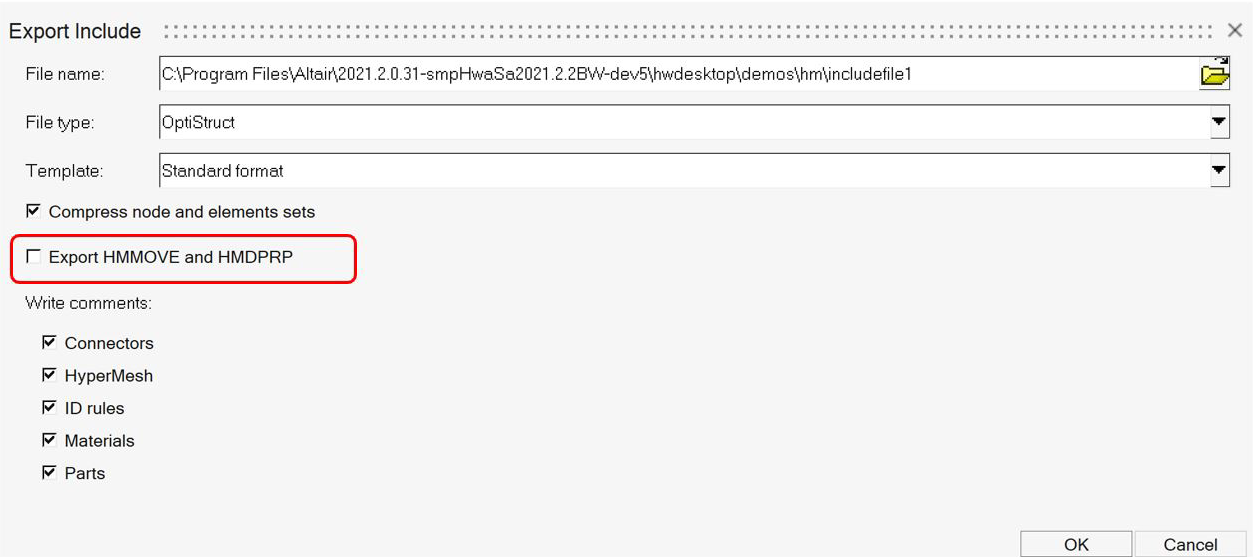
Figure 24. - Performance issue while deleting components with many loads.
- Performance issue associated with renumbering nodes in large models.
- Crash issue when folder path specified in script does not exist.
- Performance issue in selecting entities using Renumber Entities tool.
- Isolated crash issue associated with saving a model after deleting geometry.
- Inability to capture TableView images in batch mode on Windows.
- Performance issue while entering and exiting the Midsurfaces tool on the ribbon.
Known Issues
- TableView images not captured in batch mode on Linux (this has been resolved on Windows).
- For certain monitor configurations and aspect ratios, TextView and TableView images captured in batch mode may not fill the whole area in the captured images, resulting in some black space to the right of and/or below the image.
- Pinning the application to the taskbar is not working properly for legacy HyperMesh/HyperView/HyperGraph; this issue is not seen with the new HyperWorks interface.
- In a multi-window layout, if a MotionView window is active, there is a crash when swapping the position of two inactive windows; a workaround is to ensure the window being dragged for the swap is the active window (by clicking on it, for example).
Geometry
New Features
- Axisymmetry
- New Axisymmetry ribbon with tools to reduce Solids on axisymmetric surfaces and account for volume reduction.
-
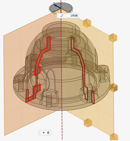
Figure 25. -
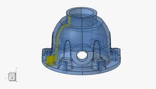
Figure 26. -
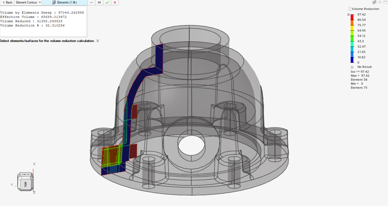
Figure 27.
Enhancements
- Units support added for Sketching tools.
- Creating sketch from FE Geometry is now supported.
- Preferences option added to delete associated entities with deleting a sketch.
- “Use Parasolid” option added for surface patch tool to enhance robustness.
- Added functionality to split tool to allow splitting of multiple lines.
- Splitting of surface using FE edges is supported.
- Feature selection enabled for defeaturing holes, fillets, and logos.
- Defeaturing fillets supports additional panel options for ignoring edges and end.
- Defeaturing cuts now supports trim-intersect functionality from the panel.
- Features editing support added.
- FE geometry surface extension capabilities enhanced.
- Surface trim using FE edges.
- CAD readers
- OCX CAD reader as well as Aveva Marine CAD readers where enhanced to populate PARTS with plate thickness and material as PDM Attributes instead of metadata. Hence, you can now generate properties using the regular Part Browser feature .
Matrix Browser
Resolved Issues
- Application crashed when using a Compose function.
- Issue caused by special characters in column labels. Special characters are now automatically stripped out.
- Columns with labels starting with a number could not be used in user equations.
- Switching off preferences option "Show Subcase and Simulation name in column header" had no effect.
Meshing
New Features
- Edit elements
-
- Smooth tool enhanced to support anchor free edge nodes, number of iterations, and keep selection.
- Element split, combine, and refine (manual) support extended for higher order elements.
- Graphical previews and pre-calculation made optional; you can switch on/off as per convenience.
- Replace tool supports coincident nodes picking and replace.
- Associate function improved. Also, surfaces and solids-level disassociate functionality added.
- Tetra meshing
-
- 0D and 1D elements are fully supported as Anchors in tetra mesh.
- Wake and Part-based refinement support added.
Enhancements
- Concept ribbon
- Doubler and Bulkhead tools are now exposed in a new Concept ribbon along with Stiffened Panel.
- Criteria/Parameter editor
-
- Added new calculation method for LS-DYNA in criteria editor.
- “Auto calculate” functionality added to calculate valid minimum and maximum size based on target element size.
- BatchMesher
- Various issues fixed addressing robustness, mesh flow, and job submission.
- Midmesh
-
- Midmesh default extraction output is FE geometry only. Geometry tools and contexts can be used to edit midmesh output for quick topology editing.
- Midmesh Align tool enhanced for mesh flow improvements and robustness.
- Comparison API
- Performance improved and memory footprint reduced.
Resolved Issues
- General 2D mesh tool face edit related application crash fixed.
- Comparison tool issues with FE geometry surfaces as input fixed.
- Solid map tool related crash issue fixed.
- Defeature holes removal tool not able to identify solid holes fixed.
- Density changes in edit elements context causing application crash fixed.
- 1D elements conversion to FE geometry for few config addressed.
- Isolate behavior is made consistent for 1D and 2D FE geometry elements.
- Snapping to points in Shape tool causing application hang addressed.
Model Build
Enhancements
- Parts supported in Mechanisms
-
- Parts can now be selected as entities when building a mechanism. This allows for mechanisms to be constructed and for representation/revision management to load the parts in the correct location, no matter what position the mechanism has been moved to.
- This simplifies modeling different mechanism positions for design studies as a single part can be moved between positions rather than building multiple models, or having multiple parts, each in the required position.
Model Verification
Enhancements
- Deviation Comparison
- Performs CAD vs CAD comparison directly on surfaces with a Match% accuracy better than cadtofeapproach. Performance is also better then cadtofeapproach option. Lower tolerance can be used to detect the mismatches.
-

Figure 28. - Detailed Comparison
- Compares components, elements, most of the solver cards and its parameters. Primary Model must be imported in the HyperWorks graphics, then Detailed Comparison Interface must be invoked and the secondary model must be selected. Comparison results are displayed on a split window with a tree structure; mismatches are highlighted in red. This can be accessed from Comparison Browser / Tools.
-

Figure 29.
Resolved Issues
- Fixed an issue in Comparison: CAD-CAD Comparison Report - Thumbnail Shading mode was not working.
- Fixed an issue in Comparison: Partial-match Option for meshing unmatched components was not working in Batch Mode.
- Fixed an issue in Comparison: Multi-variant comparison check was not working.
- Fixed an issue in Intersection: Intersections were not detected on Solid vs Surface inputs for Long tubular cross sections.
- Fixed an issue in Intersection: Intersection check was improved to handle huge models.
Known Issues
- CAD Assembly units are not recognized; thus, Meter vs Millimeter models will not be compared.
Morphing
New Features
- Morph Constraints Tool
- The Morph constraints have been migrated to a new tool, allowing you to create constraints in an easier workflow.
Enhancements
- Improved the graphical quality and precision of the Proximity morphing area preview.
- When selecting planes in the morph volume tools, plane suggestions now only appear when selecting planes (like in Symmetry) and not directions (like local orientation).
- Improved the layout of the remesh options inside the morphing tools.
Resolved Issues
- Animating a morph Shape no longer interferes with panning and rotating the model.
- Corrected motion of handles when modifying the height of some cylindrical morph volumes with cyclic symmetry.
- Fixed an issue where clicking on a morph volume after moving one of its handles could re-apply the deformation in some scenarios.
- Fixed an issue where attempting to register nodes outside of a volume would remove their registration to other enclosed volume.
Post
New Features
- Legend Entity
- Use the newly added Legend entity to create, edit, and assign custom legends to any contour, vector, or tensor plot.
Enhancements
- Preference option added to automatically set simulation to last step after loading.
- Tcl command added to retrieve derived layers for a specific data type (e.g. max, min, count, sum).
Resolved Issues
- Application crashes when using hm_getresults command.
- Play button on Plot Context does not work if plot control name is changed.
- Random application crashes when changing visualization with legends displayed.
- Application crashes when any averaging method other than None is selected along with custom entity selection.
- Application crashes when plot control entity is created via *createentity command.
- Application crashes when adding OptiStruct h5 result file in SUSE 15sp2 Linux OS.
- Layer field not filtered as per result type correctly.
- Contour plot incorrect after masking some elements.
- Application crashes when deformation is plotted on a model with only thermal results.
- Application crashes when a wrong datatype is passed with a script.
- Application crashes when any averaging method other than None is selected and Resolved in system is set to user.
Safety Tools
New Features
- New IP Impact Tool for FMVSS201 & ECE-R21 regulations
- The new IP Impact Tool allows:
-
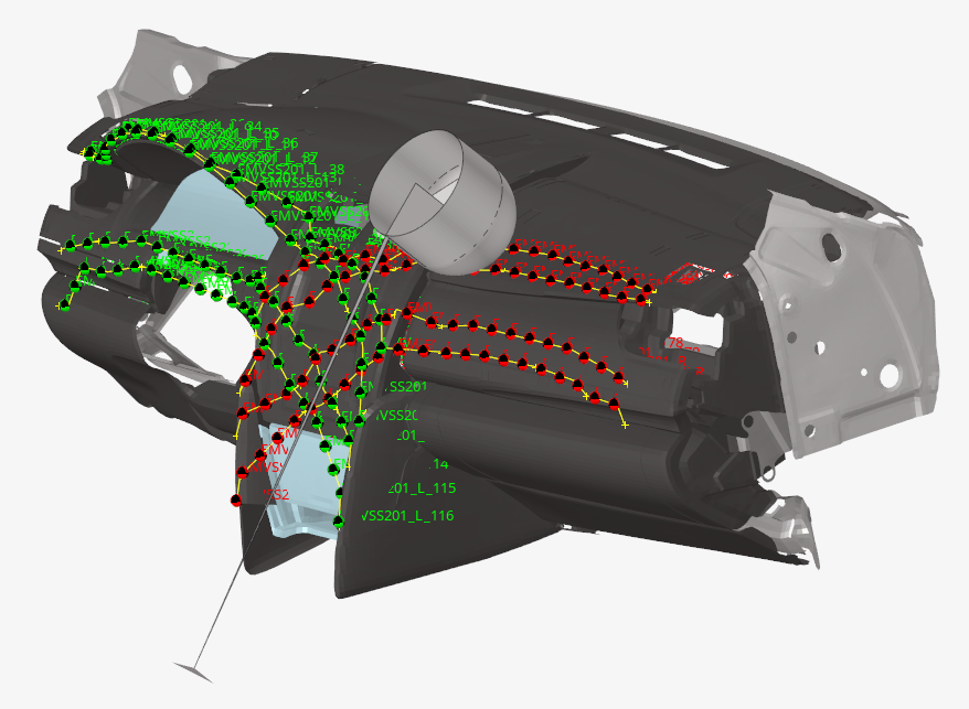
Figure 30. -
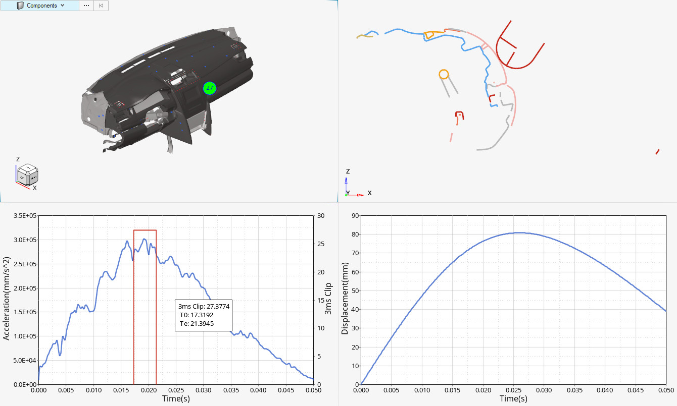
Figure 31. - Roof Crush added in Barrier Positionner Tool
- The Roof Crush load case is added to the Barrier Positionner workflow and allows:
-

Figure 32.
Enhancements
- Seatbelt Tool
-
- New wrap entity selection in seatbelt segment for better belt wrapping control and quality around dummy and seat
- Automatic update of seatbelt by selecting new path to adapt an existing belt to a new dummy/seat configuration
- Unit system (g,mm,ms) is added
- Pre-simulation tools (dummy and seat deformer)
- Unit system (g,mm,ms) is added
Skeleton Modeling
New Features
- Solid Geometry is now supported as a direct input to create the reduced order skeleton model.
- Autoweld option will stitch together the flanges for the respective sections so that each section is fully closed.
Solver Conversion
Enhancements
- Abaqus to OptiStruct conversions
-
- Hexa,COH3D8 converted to Hexa,CIFHEX
- *Hyperfoam (uniaxial, biaxial and planar test data) converted MATHE,FOAM(tab1,tab2 and tab4)
- *COHESIVE SECTION converted to PCOHE,MCOHE
- Ansys to OptiStruct conversions
-
- ANTYPE,STATIC is converted to Linear Static Analysis
- ANTYPE,MODAL is converted to Normal Modes Analysis
- ANTYPE,BUCKLE is converted to Linear Buckling Analysis
- Radioss to OptiStruct conversions
-
- /CLOAD,/FUNCT converted to FORCE,DLOAD,TLOAD,TABLED1
- /TYPE24 contact converted to CONTACT,AUTO,PCONT,PSURF
- /TYPE25 contact converted to CONTACT,AUTO,PCONT,PSURF
- Abaqus to Radioss conversions
-
- *CONNECTOR SECTION,AXIAL converted to /PROP/SPR_BEAM
- *CONENCTOR SECTION,HINGE converted to /PROP/SPR_BEAM
- PamCrash to Radioss conversions
-
- MAT105 converted to MAT36/MAT2
- MAT117 converted to MAT36/MAT2
- MAT220 converted to PROP/SPR_GENE
- TIED converted to /INTER/TYPE2
- Permas to Nastran conversions
-
- $ESET converted to SET
- $NSET converted to SET
CAD and Solver Interfaces
Abaqus Interface
New Features
- Segments Selection and Manipulation
- Individual segments can be selected from idle. Organize, delete, and other advanced options are available.
- New User Comments Entity
- A new user comments entity is implemented which allows you to add comments of your choice to the input file for the main deck and include files.
Enhancements
- Redundant Entity Management for Sets
- Allows you to realize undefined sets referred by other entities when the undefined sets come from a secondary import such as include files.
- Legacy Comments Support
- Component and Property legacy comments support are available while exporting the input file.
- Consolidate for AutoContact
- Consolidation of detected contact/tie in an AutoContact search has been re-introduced.
- Model Check Validation
- Check enabled for elements with missing property assignment.
- Contact Pair Selection for Model Change
- While defining model change, selection of a contact pair is now allowed instead of main and secondary surface.
- New Keywords
- *JOULE HEAT FRACTION
- Updated Keywords
- ALLSECTIONPTS in *ELEMENT OUTPUT
- Post-Processing
- Abaqus 2022 ODB result file reading is supported for HyperView and HyperGraph.
Resolved Issues
- Multiple issues and application errors in Load step manager are resolved.
- An issue with order in which *BEAM GENERAL SECTION is written to the input file is resolved.
- Model checker issue for kinematic coupling is fixed.
- Model checker application error issue for zero length 1D elements is resolved.
- Segmentation error on updating DCOUP3D element dependent nodes is fixed.
- Tension cut-off value for *LOW DENSITY FOAM set to zero as default is fixed.
- Search is updated to find *FRAME SECTION.
ADVC Interface
New Features
- Card Support
-
- $UserMaterial
- To define your own material properties for calculating stress. Supported for Structure Analysis.
- $UserMaterialOfHeatTransfer
- To define your own material properties for calculating stress. Supported for Latent Heat Transfer Analysis.
- $MaterialUserLibrary
- Specifies the library file name of user function used in $UserMaterial and $UserMaterialOfHeatTransfer for heat transfer analysis. You can specify only one MaterialUserLibrary document in the analysis model. Both absolute and relative file paths are supported.
Enhancements
- "Allow 2D-3D set segmenent re-parenting" option is supported in . This option allows to select shell elements over solid elements during set creation
ANSYS Interface
Enhancements
- Unblocked format supported in import for Materials, Real Block, Loads, Constraint equations, and Systems.
- Blocked format support for import of Pressure Load and Temperature Load.
- Contact surface migrated to set segment entity.
- Embedded Entity Editor support for contacts, Loadsteps, and set segments.
CAD Interface
Enhancements
- Updated Version Support (Readers)
-
- Catia V5-6 R2022 (R32)
- Catia 3D Experience R2022X
- Inspire 2021.2 & 2022
- JT 11.0
- NX 1980 (Native & Third party)
- NX 2007 (Native & Third party)
- Parasolid 34.1.188
- Solidworks 2022
- Updated Version Support (Writers)
-
- JT 10.7
- Parasolid 34.1.188
- Inspire 2021.2, 2022
*setoption and hm_getoptions API supports all cad import and export options.
Resolved Issues
- Fixed issue related to Timeout for JT files.
- Fixed issues from parts scaling for JT files.
Known Issues
- In HyperWorks 2022.1, CAD import using a third party CT based reader (ACIS, Catia, Creo, Inventor, NX third party, Solidworks, and Step formats) and CAD export for STEP format is not supported if the Linux GLIBC library is lower than version 2.28.
LS-DYNA Interface
New Features
- New LS-DYNA R13.0 Profile
- The new LS-DYNA profile is introduced to support the new solver version R13.0.
- New Systems Workflow
- The new Systems workflow provides a interactive and efficient user
experience for the creation of coordinate systems.

Figure 33. - Import of Compressed Input Decks
- It is now possible to directly import a compressed input deck.
Only the format .gz is supported.
- New Material Behaviors Entity
- The new Material Behaviors entity is used for the definition of *MAT_ADD
keywords, previously mapped to the Property entity.The Material Behaviors are also directly referenced into all *MAT keywords.
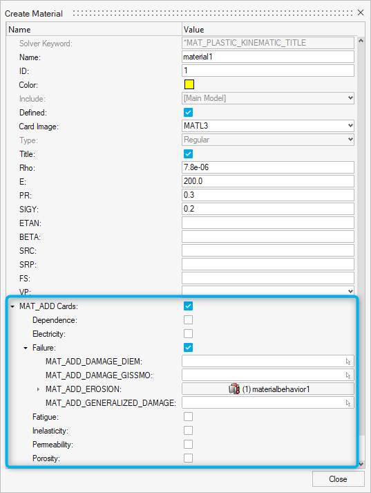
Figure 34. - New Constraints Entity
- The new Constraints entity is used for the definition of
*CONSTRAINED_INTERPOLATION_SPOTWELD keyword.
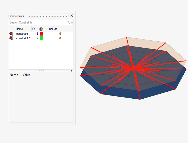
Figure 35.
Enhancements
- Solver Profiles Cleanup
- The LS-DYNA profiles R6.1 and R7.1 are no longer exposed.
- Panels and Panel Functionality Removal in HyperWorks
- Panels or panel functionalities for which an equivalent tool or workflow exists in other areas of the product (example: Browsers, Graphical entity selection, ...) are removed from HyperWorks only.
- New Calculation methods for 2D minimal mesh size criteria
- The minimal size calculation is enhanced by the addition of the LS-DYNA
specific methods ISDO=1 and ISDO=2.
Figure 36. - New Supported Keywords
- *BOUNDARY_PRESCRIBED_FINAL_GEOMETRY
- Updated Keywords
- *CONTROL_CPM, *CONTROL_ENERGY, *CONTROL_IMPLICIT_SOLUTION, *CONTROL_MAT, *CONTROL_SHELL, *CONTROL_SOLID, *CONTROL_SOLUTION, *CONTROL_SPH, *CONTROL_TIMESTEP
- Model Checker
- Check added to report a warning when a *CONSTRAINED_NODAL_RIGID_BODY is defined with a massless independent node.
Resolved Issues
- *DEFINE_TRANSFORMATION applied on multiple nested *INCLUDE_TRANSFORM are now correctly calculated.
- *SET_NODE and *CONSTRAINED_NODAL_RIGID_BODIES are now maintained in respective include on export.
- Keywords titles containing special characters like "," are now fully read.
- HM_TAGS defined in input decks are now read correctly.
- Correction in finding unused Systems.
- Correction in reading *DEFINE_CURVE when DATTYP attribute is blank.
Nastran Interface
New Features
- Import option to handle preserved nodes
-

Figure 37. - 1D meshing consolidation
- Consolidated 1D beam tools and Marine Stiffener meshing.
- Beam → Solid
- New tool to create Solids from 1D beam with standard beamsection.
-

Figure 38.
Enhancements
- 3D visualization of taper beams
- Limited to standard sections.
-

Figure 39. - Beam → Surfaces
-
- Create properties or nodal thickness on shell mesh created.
Figure 40. - Support for shell beamsections.

Figure 41.
- Create properties or nodal thickness on shell mesh created.
- Section Property tool for Elastic and Shells
-
- Section property now uses Elastic section config instead of Generic sections.
- The tool can also generates shell beamsection with auto welds.
Resolved Issues
- FE import reader crash caused by formatting of $HMNAME.
- Application error while editing elements.
- Incorrect ply thickness update in Matrix Browser for PCOMPG.
- Incorrect import of CBEAM elements.
OptiStruct Interface
New Features
- Automatic method to define a free convection setup
-
- New bulk cards CONVG and CNVGADD added to define free convection and combined free convection, respectively.
- Subcase dependent free convection are defined with CONVG subcase selection cards.
- Free convection definition can be created from Solver Browser.
- CAFLUID-based flow heat transfer
-
- New element CAFLUID added as 1D element entity in Rod config.
- New property PAFLUID to define 1D CAFLUID heat flow element.
- CACONV bulk card added to group entity to define interface for forced convection heat transfer using CAFLUID.
- Adaptive Perfectly Matched Layer(APML) for exterior acoustics
-
- New element types CACPML3 and CACPML4 to define APML element with triangular and quadrilateral base, respectively.
- PACPML to define properties for APML elements.
- Pressure penetration load to simulate fluid penetrating through the surfaces on a contact interface
-
- New bulk card PRSPENE to define pressure penetration load.
- PRSPENE loads can created from Solver Browser.
- OptiStruct specific PRSPENE checks are added in model checker.
- Shell to Solid connection
-
- RSSCON1 bulk card added to define connection between shell and solid elements.
- RSSCON1 is mapped to group entity.
- SENSOR input to activate loads
-
- New bulk cards SENSOR to define sensor input.
- SENSRAD bulk card to defined union of several sensor inputs.
- Subcase references of SENSOR and SENSRAD are defined through SENSOR in subcase information entry.
- Modal damping as a tabular function of mode index
-
- New bulk card TABDMP2 to define modal damping as a tabular function.
- TABDMP2 card is mapped to curve entity.
- MEFFMASS output in HyperMesh set based format
- MEFFSET bulk card to group element sets to output MEFFMASS output in set based format.
- Fatigue process manager template
-
- Option to write all fatigue cards into an include file.
- Seam and Spot weld options are now enabled for EN fatigue method.
- FKM2 option for Seam and Spot weld.
- Import option to handle preserved nodes
-
Figure 42. - Section Property tool for VABS
-
- Generates VABS *dat file from intersection of plane with Shell composites.
- Updates 1D beam with PBEAML property using VABS *.dat file.
- Limited to OptiStruct interface.
-
Figure 43. - 1D meshing consolidation
- Consolidated 1D beam tools and Marine Stiffener meshing.
- Beam → Solid
- New tool to create Solids from 1D beam with standard beamsection.
-
Figure 44.
Enhancements
- Pre-tension manager now allows CBUSH elements to define preload.
- JOINTG element enhanced to support newly added combination joints in OptiStruct.
- JOINTG element enhanced to grounded Joint input.
- MATFAT bulk card enhanced to include SNTBL continuation line for xy format inputs.
- Mechanism browser enhanced to include Set as an input in addition to component input.
- Multiple input selection for combined loads, for example: LOADADD, SPCADD, PTADD, and so on.
- PCONT bulk card enhanced to input Main/Secondary surface for Auto contact in OptiStruct Explicit analysis.
- SUPORT1 bulk card enhanced to input grid set.
- Free format (comma separated) export for individual include file export.
- MODCHG bulk card enhanced to input TIE contacts.
- Non-Linear transient analysis type enhanced to input CNTSTB, MOTNJG and LOADJG subcase selection inputs.
- PCONT bulk card enhanced to reference CLRNC bulk card.
- LOADJG subcase selection input for Linear static analysis.
- 3D visualization of taper beams
- Limited to standard sections
Figure 45.
- Limited to standard sections
- Beam → Surfaces
- Create properties or nodal thickness on shell mesh created.
Figure 46. - Support for shell beamsections.
Figure 47.
- Create properties or nodal thickness on shell mesh created.
- Section Property tool for Elastic and Shells
- Section property now uses Elastic section config instead of Generic sections.
- The tool can also generates shell beamsection with auto welds.
Resolved Issues
- Bead fraction response type selection as design constraint.
- Cannot change local coordinate system for pattern repetition in DTPL card.
- FE import reader crash caused by formatting of $HMNAME.
- Move TIE bulk card from Explicit analysis to Contact folder in Solver Browser.
- Application error while editing elements.
- Incorrect ply thickness update in Matrix Browser for PCOMPG.
- MAT9OR card name is now consistent with OptiStruct documentation.
- Incorrect import of CBEAM elements.
PAM-CRASH Interface
New Features
- New Comments Entity
- Keyword CDATA is supported as new Comments entity type and moved out from the Property entity type.
- New Keywords
- STAGEFILES
Enhancements
- ID and Reference Parameterization
- Extended support of keyword ID parameterization and parameterization of ID references in other keywords of PAM-CRASH like CNTAC, MASS, MATER, MMAT, MPART, PART, NSMAS, RETRA, SELOUT, SLIPR, TIED, THNOD, THLOC, THNPO.
- Metric Reference Geometry Include
- METRIC Reference Geometry data in an external file is listed as a separate include file of type Metric.
- Updated Keywords
- CDATA
Resolved Issues
- Missing fields parameterization support in the keywords PART, AIRBAGCHECK, CKCTRL, CCTRL.
- Rigid (RBODY, MTOCO, LINCO, NODCO, OTMCO) entities organized in respective includes upon import.
- Evaluation of Transformation is based on TRANSd value, in the direction of IDNODT1 and IDNODT2.
- Resolved import issues related to Include File path when nested or multi-level folders exist
- Resolved data import issues with THIN_WALL in 2012 -2016 profiles, MATYP 371 in 2016-2019 profiles, and SENPT or SENPTG IDs conflicting with SHELL or SOLID.
- Modular keywords (NUMPAR, MMAT) Type is listing in TOC - Entity View browser.
Radioss Interface
New Features
- New Constraints Entity
- The new Constraints entity is used for the definition of /MERGE/RBODY
keywords.

Figure 48. - New Systems Workflow
- The new Systems workflow provides a interactive and efficient user
experience for the creation of coordinate systems.
Figure 49. - Import of Compressed Input Decks
- It is now possible to directly import a compressed input deck.
Only the format .gz is supported.
Enhancements
- Solver Profiles Cleanup
- Radioss profiles lower than 2017 are no longer exposed.
- Panels and Panel Functionality Removal in HyperWorks
- Panels or panel functionalities for which an equivalent tool or workflow exists in other areas of the product (example: Browsers, Graphical entity selection, ...) are removed from HyperWorks only.
- New Supported Keywords
- /ANIM/VECT/PCONT2
- Updated Keywords
- /ADYREL
- Migration of /ADMESH/SET to Set entity
- The keyword /ADMESH/SET, previously mapped to the Property entity, is now defined in the Set entity.
Resolved Issues
- Display orientation of /SKEW/MOV2 is corrected.
- Display orientation of /SKEW and /FRAME depending on the DIR value is corrected.
- /SENSOR/RWALL is now correctly written on export.
- Radioss /SET/GENERAL are maintained as in import/export as an unsupported keyword.
- /MAT/LEE_TARVER in now correctly written on export.
- Correction in Set assignment in /RBODY Entity Editor.
- Correction in /TABLE support.
- Correction in /TH keywords when reference entity is renumbered. The renumbered ID is now correctly updated in /TH keyword.
- Correction in export of /SURF/SEG when defined on 2nd order hexa elements.