Interface
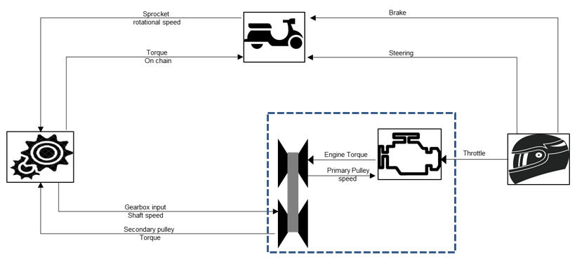
CVT Powertrain is described by a Control State Equation (CSE). The inputs to the powertrain are throttle and gearbox input shaft speed. The output is the secondary pulley torque. There are two optional clamping forces inputs to the powertrain. The CVT property file allows to choose between a mechanical CVT or electric/hydraulic CVT. By default, MS models a mechanical CVT and the clamping forces are calculated based on parameters in the CVT property file.

 Figure 1. Schematic of CVT Powertrain
| Parameter | Details | Unit | Symbol |
|---|---|---|---|
| BELT_TYPE | Type of variator belt (rubber, steel, etc) Currently the belt is considered rigid despite the value of this parameter | ||
| CLAMP_MECH | Mechanism to generate clamping force. It can be CENTRIFUGAL or user-defined name | ||
| RP_MAX | Maximum running radius of belt on Primary pulley | Length |  |
| RP_MIN | Minimum running radius of belt on Primary pulley | Length |  |
| RS_MAX | Maximum running radius of belt on Secondary pulley | Length |  |
| RS_MIN | Minimum running radius of belt on Secondary pulley | Length |  |
| THETA | Half of Pulley wedge angle | Angle |  |
| BELT_LENGTH | Length of the belt, it is assumed constant | Length |  |
| MU_STATIC | Friction value between belt and pulley when belt does not shift |  |
|
| MU_DYNAMIC | Friction value between belt and pulley when belt slips on pulley |  |
|
| BELT_MASS | Mass of the belt | Mass |  |
| PULLEY_DISTANCE | Distance between primary and secondary pulley | Length |  |
| NO_ROLLERS | Number of rollers |  |
|
| ROLLER_MASS | Mass of a roller | Mass |  |
| P_SHEAVE_ANGLE | Inner angle of the moving sheave in primary pulley | Angle |  |
| KP | Spring stiffness in primary pulley | Force/Length |  |
| KP_LOAD | Preload of the spring in secondary pulley | Length |  |
| KS | Spring stiffness in secondary pulley | Force/Length |  |
| KS_LOAD | Preload of the spring in secondary pulley | Length |  |
| KT | Torsional spring stiffness | Force*Length/Angle |  |
| KT_LOAD | Preload torsion angle | Angle |  |
| HELIX_RAD | Helix radius | Length |  |
| HELIX_ANGLE | Helix angle | Angle |  |
| RADIAL_SHIFT_PROFILE | The variation of the roller radius from rotating shaft and ramp angle with respect to the axial shift of moving sheave of the primary pulley | Length vs Length and Angle vs Length |  and and  |
| CMM | CMM coefficient and thrust ratio (dimensionless) variation with respect to radius ratio | 1/(Force*Angle) |
| Output Name | Request ID | Elements | Component | Unit | |||
|---|---|---|---|---|---|---|---|
| Throttle position, input throttle, static throttle | 1 | 1 | Modified Throttle position | 0-1 | |||
| 2 | Throttle demand | 0-1 | |||||
| 5 | Throttle modulation indicator | ||||||
| Radius ratio, Radius - Pr. pulley, Radius - Sec. pulley, Alpha, Beta | 2 | 1 | Geometric gear ratio/pulley running radius ratio | ||||
| 2 | Primary Pulley radius | Length | |||||
| 3 | Secondary Pulley Radius | Length | |||||
| 5 | Primary Pulley Wrap Angle | Angle | |||||
| 6 | Secondary Pulley Wrap Angle | Angle | |||||
| Eng. omega (rad/s), Eng. omega (rpm), Engine trq., [d/dt] Engine trq. | 3 | 1 | Engine Speed | RPM | |||
| 2 | Engine Speed | Rad | |||||
| 3 | Engine Torque | Force*Length | |||||
| 5 | Engine Speed Derivative | Rad/Sec | |||||
| Pr. pulley trq., Sec. pulley trq., Pr. pulley frc., Sec. pulley trq., k_thrust | 4 | 1 | Primary Pulley Torque | Force*Length | |||
| 2 | Secondary Pulley Torque | Force*Length | |||||
| 3 | Primary Clamping Force | Force | |||||
| 5 | Secondary Clamping Force | Force | |||||
| 6 | Stationary Clamp Force Ratio | ||||||
| 7 | Belt Slip | ||||||
| CVT pri. pulley [Sh. shft., Rad. shft., Ramp ang., Spr. frc., Fly. wt. frc.] | 5 | 1 | Primary pulley sheave axial shift | Length | |||
| 2 | Rollers radial shift | Length | |||||
| 3 | Primary pulley sheave ramp angle | Angle | |||||
| 5 | Primary pulley spring force | Force | |||||
| 6 | Centrifugal force by fly weights/rollers | Force | |||||
| 7 | 0 | ||||||
| CVT sec. pulley [Sh. shft., Spr. rot., Helix frc., Spr. frc., Spr. trq., Trq. feedback] | 6 | 1 | Secondary pulley sheave axial shift | Length | |||
| 2 | Secondary pulley spring rotation | Angle | |||||
| 3 | Helix Force | Force | |||||
| 5 | Secondary Pulley Spring Linear Force | Force | |||||
| 6 | Secondary Pulley Spring Torque | Force*Length | |||||
| 7 | Torque Feedback | Force | |||||
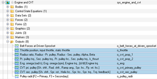
 Figure 2.
 In MotionView these six outputs access the POWERTRAIN_REQ “USER(0,id)” to display the different plots in HyperGraph.
 Figure 3.