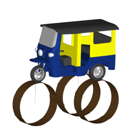
Drum Road
Typical inputs for modeling a Drum Road are the drum’s dimensions (diameter and length), the drum’s position and orientation relative to the wheel center, the number of cleats, their position and orientation on the drum, and their shape, and finally the drum’s rotational speed. Here, however, the drum’s diameter is inferred from the drum surface profile.
The drum surface profile may be specified in a table or read from .csv file. In either case the first column of the table or .csv file gives the distance along the circumference of the drum and the second column gives the drum height. The first distance value must be zero and last distance value gives the circumference of the drum. Hence the drum diameter is last distance value divided by PI. The drum height is linearly interpolated with respect to circumferential distance.
When using the Drum Road, the vehicle or wheel/tire riding on the drum should have no or limited motion relative to the drum to prevent the vehicle or wheel/tire from falling off the drum. There is no check for alerting you about the movement of vehicle away from the drum. However, if at the beginning the vehicle is outside the drum’s x range it will fall to the bottom of the drum. The drum’s width is infinite during simulation (even if the drum graphics are finite).
Vehicle Model Requirements
The steering wheel joint must be locked as it should not induce any steering.The vehicle should not have longitudinal motion. There is no check for alerting you about the movement of vehicle away from the drum. The drum’s width is considered to be infinite by the solver.
A joint allowing the vehicle to pitch, roll, yaw translate along vertical direction should be available. If static simulation fails, it is suggested to try increasing the maximum number of iterations and reducing the stability value in the “static” tab in simulation settings.
Property File
- Selecting a Drum Road
- The model block determines what kind of road the file specifies and in the case of a
drum road also selects how the drum profile and drum velocity are specified. To
specify a drum road, set METHOD and ROAD_TYPE as shown below:
Parameter Type Valid Values Description METHOD string '2D' Selects the family of two-dimensional roads. TYPE string 'DRUM_PROFILE' Selects a drum road. DRUM_SPEC string 'TABLE' or 'filename' Set DRUM_SPEC = ‘TABLE’ to give the drum surface profile in a table in the [PARAMETERS] block. Set DRUM_SPEC to a file to read the drum surface profile from a .csv file. For example:
See Specifying the Drum Profile below.DRUM_SPEC = ‘..\roadProperties\drumProfile_2.csv’DRUM_VELOCITY string 'TABLE' or 'filename' Set DRUM_VELOCITY = ‘TABLE’ to give the drum surface velocity in a table in the [PARAMETERS] block. Set DRUM_VELOICTY to a file name to read the drum surface profile from a .csv file. For example:
DRUM_VELOCITY =
                            ‘..\roadProperties\drumVel_2.csv’
See Specifying the Drum Surface Velocity below.- Example MODEL block
-
$------------------------------MODEL
[MODEL]
 METHOD             = '2D'
 ROAD_TYPE          = 'DRUM_PROFILE'
 DRUM_SPEC          = ‘TABLE’
 DRUM_VELOCITY      = ‘TABLE’
- Specifying the Drum Profile
- You specify the drum profile as the incremental height (h) above the nominal drum
radius verses distance travelled along the drum circumference. The first value of
distance must be 0.0 and the last value of distance determines the drum circumference.
The drum heights may be either positive or negative. Negative values are depressions
in the drum.
You specify the drum profile either in a table in the PARAMETERS block of property file or in a comma separated values (.csv) file that you reference from the property file.
- Table
- To specify the drum profile using a table in the PARAMETERS block set
DRUM_SPEC = ‘TABLE’ in the [MODEL] block, for
example:
[MODEL] DRUM_SPEC = ‘TABLE’ [PARAMETERS] (DRUM_PROFILE) {distance height} 0000.0, 0 1000.0, 0 1050.0, 50 1100.0, 0 3000.0, 0 3050.0, -50 3010.0, 0 4000.0, 0 5000.0, 0 - File
- To specify the drum profile using a comma separated values file, set DRUM_SPEC
= ‘filename’, for
example:
[MODEL]
  DRUM_SPEC = '..\RoadFiles\drumProfile.csv'
You can specify the file using either absolute path or a path relative to the road property file. The first row of .csv file must contain column heading of ‘distance’ and ‘height’ with the subsequent rows containing values for the drum profile. The first distance value must be zero (0.0) and the last value gives the drum circumference. For example:distance, height 0.0, 0.0 1.0, 0.0 2.0, 0.1 3.0, 0.1 4.0, 0.2
- Specifying the Drum Surface Velocity
- You specify the drum surface velocity (not drum rotational velocity) as a
time-velocity table. Values of time in the table or file must be monotonically
increasing, and velocity is linearly interpolated with time. For values of time
greater than the last value in the table, the last value of velocity is used. For
values of time less than the first value in the table, zero is taken.
You can specify the drum velocity either in a table in the PARAMETERS block of property file or in a comma separated values (.csv) file that you reference from the property file.
- Table
- To specify the drum profile velocity in a table:
[MODEL] DRUM_VELOCITY = ‘TABLE’ [PARAMETERS] (TV_TABLE) { TIME, VEL } 0.0 1.0 0.2 1.0 - File
-
To specify drum surface velocity in a .csv file in the MODEL block set DRUM_VELOCITY to a filename:
[MODEL]
  DRUM_VELOCITY = '..\RoadFiles\velocityInput.csv'
You can specify the file using either absolute path or a path relative to the road property file. The first row of .csv file must contain column headings of ‘time’ and ‘vel’ with the subsequent rows containing values for the drum velocity. For example:time, vel 0.0, 10.0 1.0, 10.0 2.0, 10.1 3.0, 11.0 4.0, 12.0
- Drum Positioning
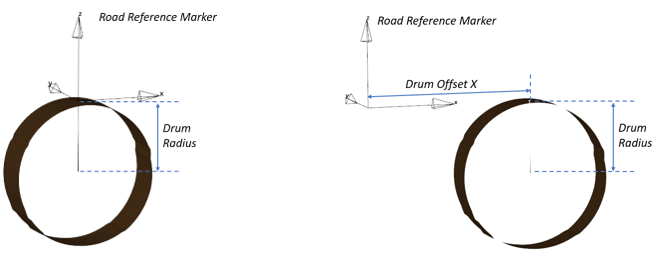
- By default, the drum is automatically positioned at the tire contact patch of the
AutoTire it was specified. The Drum center is located below the tire patch with a
distance Z of the Drum radius.
 Figure 1. Default Drum PositionThe drum can be place at a different location by using the offset option in the road file .rdf. When this option is used, the drum road refers to the road reference marker.
 Figure 2. The X, Y, Z offset must be given using the following terms in the .rdf file:
DRUM_CENTER_X_OFFSET = -1500
$DRUM_CENTER_Y_OFFSET = -750
$DRUM_CENTER_Z_OFFSET = 0
It is not necessary to give all the coordinates. The above example contains only the X location of the drum center (the Y and Z location has been commented out). In such case the value of Y and Z has no offset and will be the same as indicated in the default definition, that is, placing the drum’s surface below the tire.
Each tire in the vehicle model can receive a drum road file, with this approach you can specify different movement and road irregularity for a particular drum.
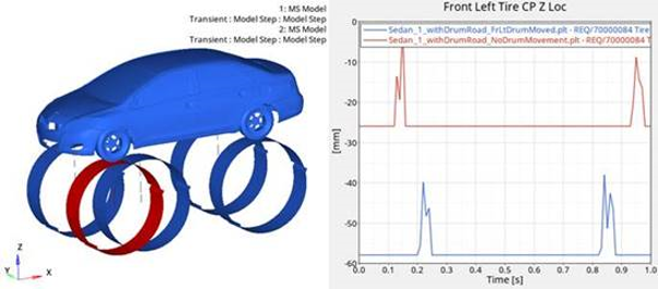
To enter a different drum road at each tire in a pair defined entity, the left-right symmetry of the AutoTire entity panel must be removed to enable right and left road definition. Figure 3. The image below shows the comparison of the front left tire's drum offset X -1500mm.
 Figure 4. Drum Movement
 - Specifying Drum Graphics Parameters
- The drum’s graphics require the input of drum width and spacing between subsequent
nodes for creating mesh. Width is only for providing a reasonable drum size. However,
the solver code considers the drum to be infinitely wide.
[GRAPHICS]
  WIDTH     = 500  $ width of drum for graphics
  ROAD_INCR = 50   $ distance between two nodes along the surface