Use the Headers panel to add headers and footers
to your video images, specify font colors, and access the Font dialog.
From the Media ribbon, click the Headers tool to
display the panel.Figure 1.
Video image headers are titles displayed at the top of a window, while video image
footers are titles displayed at the bottom of a window. Each video window can
display a header and a footer.
Figure 2.
Option
Description
Header and Footer tabs
Titles for video image headers and footers are entered in the text box
for Header and Footer. Press Return to add new
lines.
Font
Different font attributes can be specified for each line of header or
footer text. There are three user-definable styles available:
Line 1 is the style assigned to the top line.
Line 2 is the style assigned to the middle line.
Line 3 is the style assigned to the third line and all lines
thereafter.
After selecting one or more line boxes, click the font button, , to
activate the Font Selector dialog. From the Font Selector dialog, you
can change the font style, type, and size. Use the color palette to
specify the font color of the selected line.
 Figure 1.
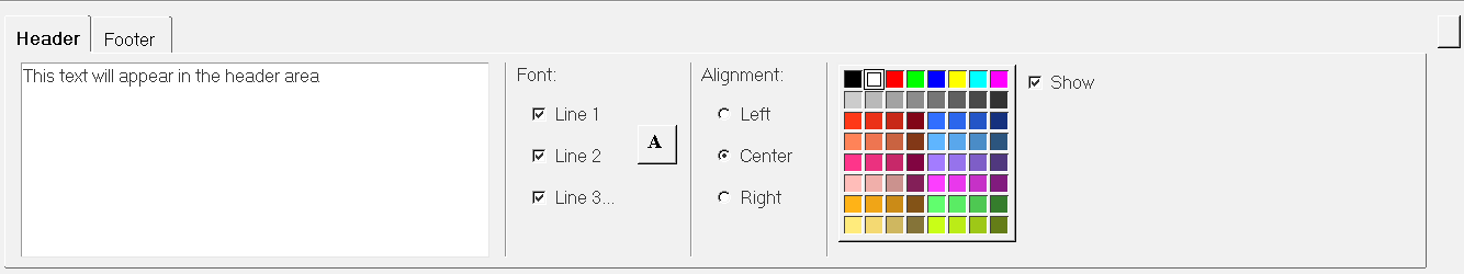
 , to
activate the Font Selector dialog. From the Font Selector dialog, you
can change the font style, type, and size. Use the color palette to
specify the font color of the selected line.
, to
activate the Font Selector dialog. From the Font Selector dialog, you
can change the font style, type, and size. Use the color palette to
specify the font color of the selected line.