Create Stiffened Panel Mesh
Create a quad-dominant mapped mesh from a network of orthogonal lines for global FE model creation. Beam/Bar/Rod elements are created around panel edges.
Restriction: Only available for Nastran and OptiStruct
solvers.
Use this tool to:
- Create mapped quad mesh using orthogonal lines that form rectangular panels.
- Create quad surface regions automatically using boundary lines.
- Create 1D stiffeners that surround panels.
- Apply a panel property per panel.
- Generate a Stiffened Panel PartAssembly with Panels and Stiffeners underneath.
Note: It is recommended that your model have orthogonal
lines.
-
From the Concept ribbon, click the Stiffened Panel
tool.

Figure 1. -
Select lines.
- Select a collection of parallel lines that define “longitudinal stiffeners”.
- Select a collection of parallel lines that define “lateral stiffeners”.
Ideally, the two sets of lines are selected form an orthogonal network of lines from which panel surfaces are inferred.
Figure 2. -
Click
 on the guide bar to select
options for model organization.
on the guide bar to select
options for model organization.
- Model Organization
-
- Create geometry and mesh in current component.
- Create a new component to store panels and stiffeners
- Create Part Assembly:
- Stiffener Prefix
- Give a prefix to name stiffener components/parts per lateral/longitudinal directions, the default being Frames & Stringer.
- Delete Geometry
- Select to keep panel surfaces (organized with panel mesh) or delete after panel mesh.
- Optional:
Click
 in the microdialog to flip
the red arrow direction, which illustrates on which side of the panels
stiffeners will be created.
in the microdialog to flip
the red arrow direction, which illustrates on which side of the panels
stiffeners will be created.
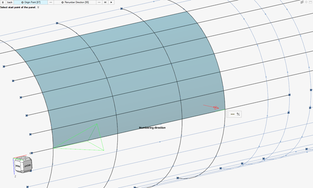
Figure 3. -
Define the mesh size and stiffener property.
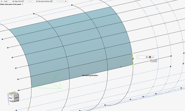
Figure 4.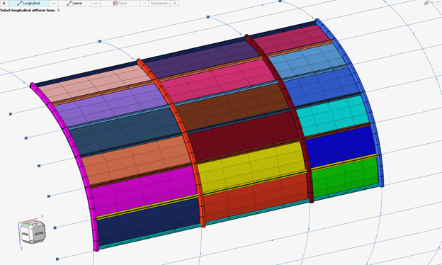
Figure 5.