Mechanism Browser
Create and articulate a kinematic mechanism based on FE mesh using the Mechanism Browser.
Figure 1.
You can undo and redo actions made in the Mechanism Browser using the Undo and Redo commands on the Restore toolbar.
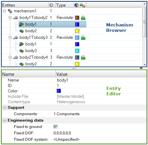
Figure 2.
| Column | Description |
|---|---|
| Entity | Lists the mechanism, joints, bodies, and constraints in your model. |
| ID | Displays the mechanism, joints, bodies, and constraints IDs. |
| Type | Displays the joint or constraints type. |
| Color | Displays the joint and body entity colors. Body color is different from the component color set-up in the Model Browser. The body color is activated when a body is in Review mode. |
| Lock level | Displays the lock level of a joint (green = free joint, yellow = locked joint). |
Entity Editor
The Entity Editor is used to assign, modify and quickly view the attributes defined inside Mechanism Browser entities.
For example, once you create a new body or select a body in the browser, the Entity Editor opens and displays the bodies corresponding attributes, which you can view and modify.
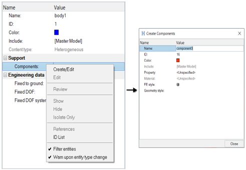
Figure 3.
Context Menu
Supported Entities
- Bodies (
 ) define
a kinematic assembly made of FE parts or nodes, which can be selected in the
Entity Editor. To create a body, right-click on
the Mechanism and select from the context menu.
) define
a kinematic assembly made of FE parts or nodes, which can be selected in the
Entity Editor. To create a body, right-click on
the Mechanism and select from the context menu. - Joints (
 ) define
the kinematic relationship between two bodies (for the following joint
types: Ball, Cylinder, Revolute, Slider) or three bodies (for the
DoubleSlider joint). To create a joint, select two bodies to connect in the
browser, then right-click and select Connect from the
context menu. For the DoubleSlider joint, the
third body has to be defined in the Entity Editor.
) define
the kinematic relationship between two bodies (for the following joint
types: Ball, Cylinder, Revolute, Slider) or three bodies (for the
DoubleSlider joint). To create a joint, select two bodies to connect in the
browser, then right-click and select Connect from the
context menu. For the DoubleSlider joint, the
third body has to be defined in the Entity Editor. - Constraints (
 ) define
kinematical constraints on a body at a specified node or point
location.
) define
kinematical constraints on a body at a specified node or point
location.
Supported Keywords Exported in Solver Deck
The mechanism information is embedded in the input deck using keywords following the /END (for Radioss), *END (for LS-DYNA), ENDDADTA (for OptiStruct/Nastran) and *END STEP (for Abaqus).
- $ASSEMBLY defines a body with the following
attributes:
- Assembly ID
- Assembly name
- Number of part sets and related set IDs
- Number of parts and related part IDs
- Number of node sets and related set IDs
- Locked degrees of freedom
- Optional local coordinate system
- $CONNECTION defines a joint between assemblies with the
following attributes:
- Connection name
- Assembly ID #1
- Assembly ID #2
- Connection position (defined by Node IDs or connection position coordinates)
- Joint limits in + and - directions
- Current joint distance/angle value
- Lock level
- Assembly ID #3 (for the Double Slider only)
- Scale factors for relative displacement between Assembly #3 and Assembly #1 and #2
- $POSITION defines, for a stored position, the position
information for the mechanism’s assemblies with the following attributes:
- Position name
- Assemblies position matrixesNote: The Reference and Initial positions should never be deleted inside the mechanism.
- The following connection keywords can be defined depending on the type of
joint created:
- $CONNECTION_PIN defines a ball joint
- $CONNECTION_HINGE defines a revolute joint
- $CONNECTION_CAM defines a cam joint
- $CONNECTION_LINE defines a cylindrical joint, or a double slider joint if assembly ID #3 is defined or a slider joint has the #HM_SLIDER_JOINT comment defined before the name of the connection
Create Mechanisms
Create a mechanism for Abaqus, OptiStruct, and Nastran profiles.
Mechanisms are created using a manual approach only.
-
From the Mechanism Browser, right-click and select .
You will see the mechanism created with bodies as shown in the following image.
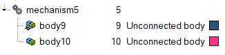
Figure 4. -
After the bodies are assigned components, right-click and select both bodies to
create the desired connection type.
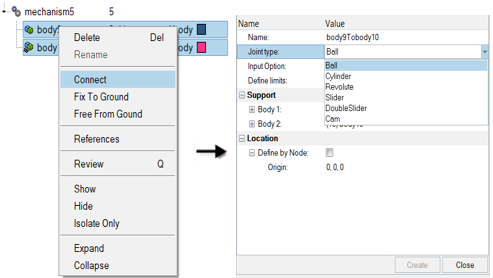
Figure 5.
Modify the Position of Mechanisms
-
In the Mechanism Browser, right-click on a mechanism and
select Actuate Mechanism from the context menu, then choose from one of the following:
- Choose Translate to open the Entity Editor and select a Node/Constraint, give a
Direction of motion, and define the Magnitude of the translation to
apply.The Magnitude can also be modified, using the up and down arrow buttons. Moreover, you can control the increments of the operations by changing the Increment value.
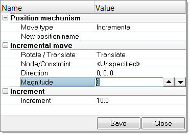
Figure 6. - Choose Rotate to open the Entity Editor, select a Body, define a Rotation axis, a
rotation center (Base point), and provide the Magnitude of the rotation to
apply to the body.The Magnitude can also be modified, using the up and down arrow buttons. Moreover, you can control the increments of the operations by changing the Increment value.
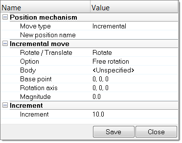
Figure 7. - Choose Target Point to open the Entity Editor, select a Node and define its Target
location. Click Move to calculate the position of
each body to bring the selected node to the target location or the nearest
location, depending on joints limit values.This option can be applied on a set of nodes and targets, by setting Multiple pairs to Yes.
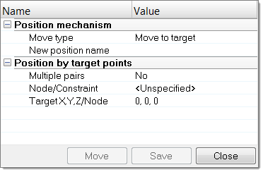
Figure 8.
- Choose Translate to open the Entity Editor and select a Node/Constraint, give a
Direction of motion, and define the Magnitude of the translation to
apply.
Modify the Position of Joints
- In the Mechanism Browser, right-click on a joint and select Move from the context menu.
-
Modify the position of the joint.
- In the graphics area, click-and-drag the manipulator.
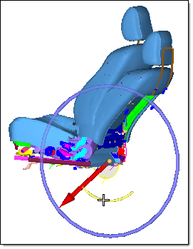
Figure 9. - In the Entity Editor, modify the Current angle
of the joint.
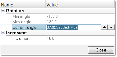
Figure 10.
- In the graphics area, click-and-drag the manipulator.
- Change the Increment value to control the increments of the operation.