Tutorial: Coupled Analysis Using OptiStruct Dynamic Link
Perform a coupled extrusion and die deflection simulation using OptiStruct dynamic link.
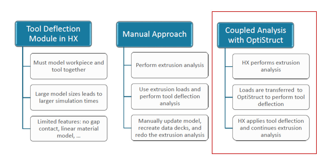
In this Tutorial we assume, flow analysis setup is already setup as mentioned in Tutorial: Solid Profile Extrusion and Tutorial: Hollow Profile Extrusion
Load Model
Organize Tool Components
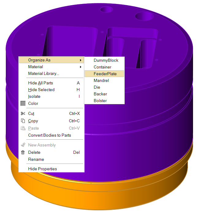
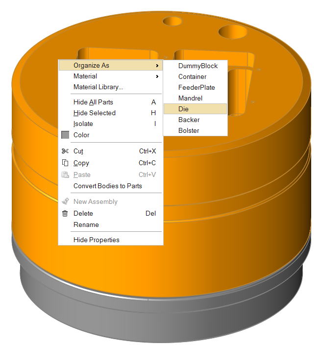
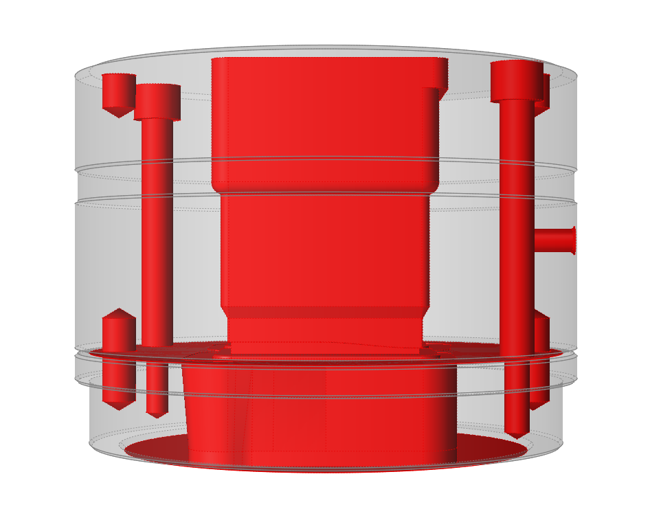
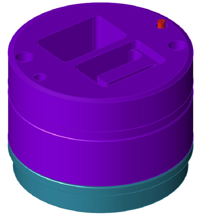
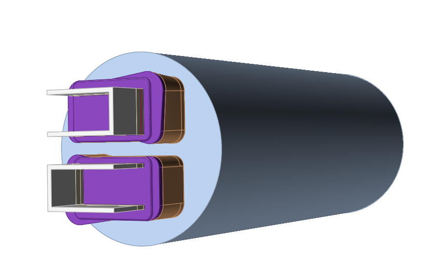
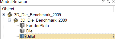
This model contains two tool components, the feeder plate and die plate, which need to be organized.
Simplify Geometry
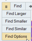
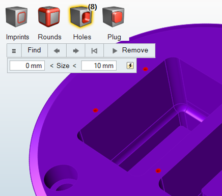
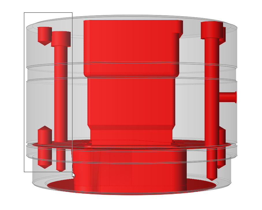
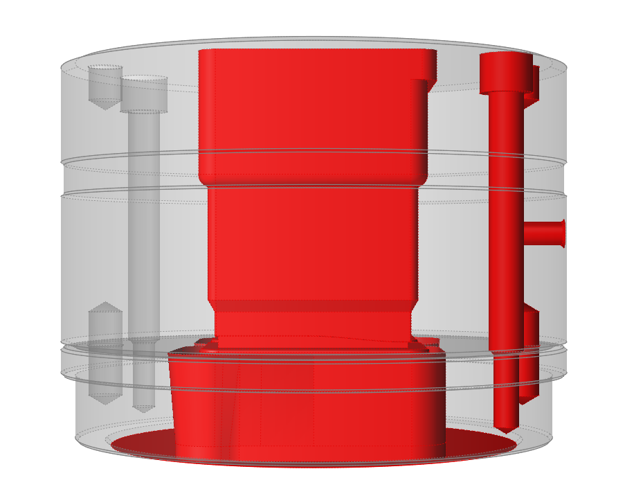
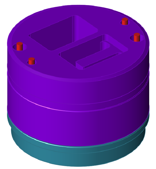
The Simplify tools can be used to clean up problem areas in the geometry before running an analysis. They are used to delete extraneous lines, surfaces, and other components in the model and to remove unnecessary features such as holes used for instrumentation. This simplifies meshing and reduces the mesh size.
Create Load Faces
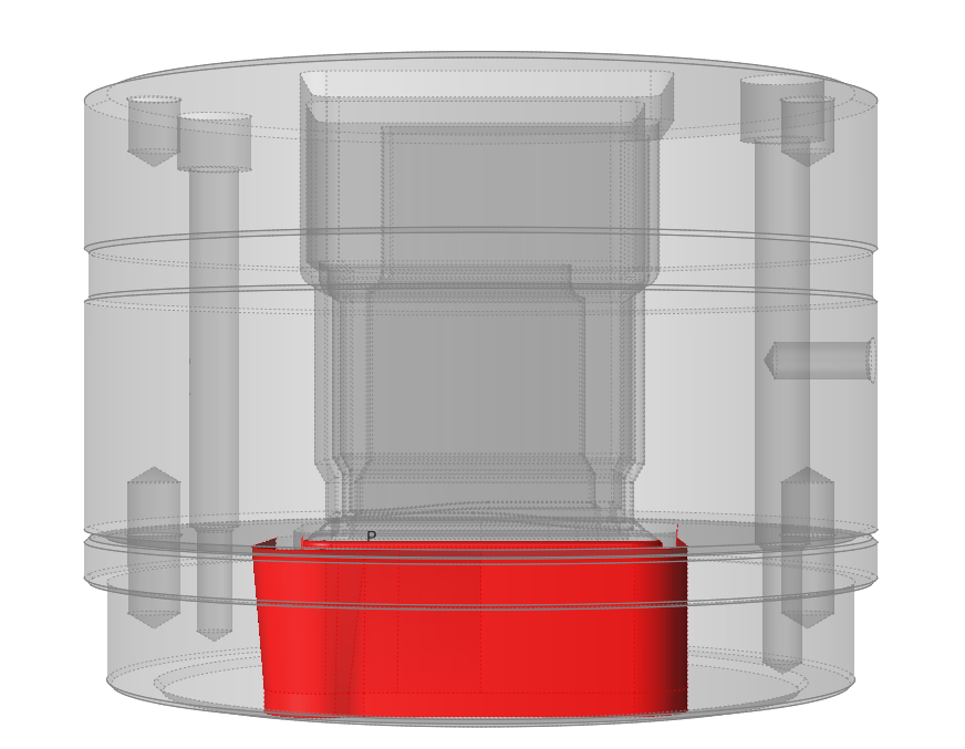
Create load faces where the material touches the tool geometry.
Workpiece material flowing inside the die exerts a load on tool surfaces and faces which are common between the workpiece and tool bodies. These are called load faces. Surfaces such as pin holes and relief regions are not in contact with the workpiece and should not be part of the load faces.
Create Constraints
The BCS tool is used to manually create constraints on appropriate surfaces.
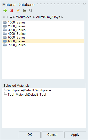
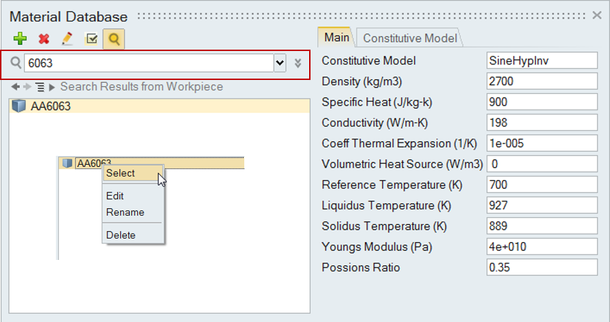
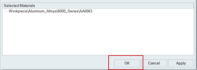
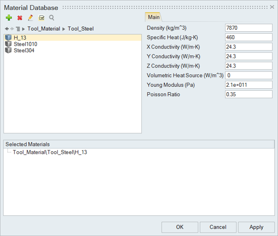
Select the Material
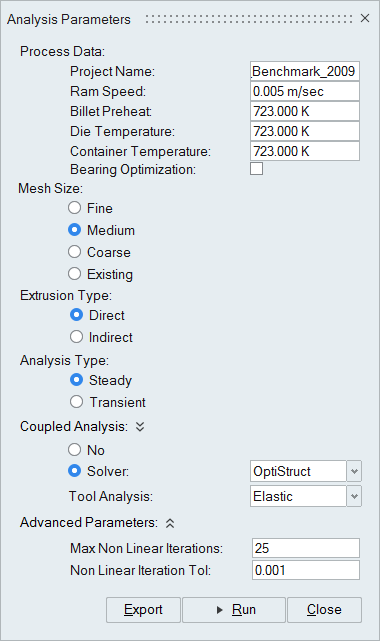
Specify Process Parameters and Simulate
| Status after submitting the job |
 |
| Status after meshing is completed |
 |
| Status when job is running in the solver |
 |
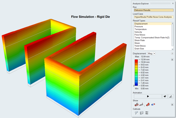
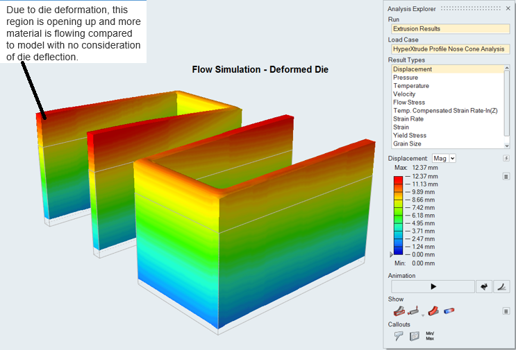
View Simulation Results
