On the left-most side of the panel is the Rakes list. The Streamlines status is also
shown in this listing. When streamlines have been created from a rake, the Streamlines
status changes from N/A to Available.
After streamlines have been created, deactivating the check box next to the rake will
hide the streamlines group in the graphics area. The same Show/Hide functionality can
also be accessed by right-clicking any rake item (see below for additional information
on Show/Hide).
You can sort the items in the Rakes list by clicking the Rakes or Streamlines
headings.
Add
Adds a new rake to the list. The newly added rake is automatically labeled and is
added to the bottom of the list. To change the name of a rake, right-click the current
name, enter a new name into the Rename dialog and click
OK.
Delete
Deletes the selected Rake/Streamline pair(s) from the list.
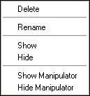
You can access the following options by right-clicking anywhere within the Rakes list: Figure 1.
Delete
Deletes the selected Rake/Streamline pair(s) from the list.
Rename
Displays the Rename dialog, which allows you to rename the
selected Rake.
Show
Displays the selected Rake/Streamline pair(s) in the graphics area and activates the
corresponding check box(es).
Hide
Hides the selected Rake/Streamline pair(s) in the graphics area and deactivates the
corresponding check box(es).
Note: To select multiple items from the Rakes list, press the Shift or Ctrl key on the keyboard + the
left mouse button.
Show Manipulator
Displays the graphical manipulator in the graphics area for the currently selected
rake/streamline. The Streamlines graphical manipulators allow you to modify the
location and shape of the rake interactively by scaling, translating, or rotating the
line, plane, or area using a manipulator specific to the rake type (Line, Plane, or
Area).
Note: Area rakes without the Evenly distributed option activated cannot be graphically
manipulated.
The graphical manipulator is linked to the entity display, therefore if a streamline
rake is not displayed, the display of the graphical manipulator is also turned
off.
Hide Manipulator
Hides the graphical manipulator for the currently selected rake/streamline in the
graphics area.
In addition, you can use the options available in the Results Browser to control the
visibility, color and transparency of a rake/streamline (including the rake outline).
Rakes Settings
The following options are applied to the rake currently selected in the Rake list when you
click Save Settings:
Rake Type
Allows you to select the rake type for the active (selected) rake:
Line
Rake defined by two end points (the definition of end points is described
below).
Plane
Rake is defined by three points (N1, N2, N3) or by a cross section.
Area
Rake defined by the surface/area of a component collector.
Entity selector
The entity selector allows you to select, or change, the two end nodes or entities
which will be used to define the rake.
N1, N2
If a Line rake type is selected: the node/vector entity selector (N1, N2) and
the Select by ID dialog can be used to select your desired nodes. HyperView will automatically provide the X, Y, Z positions
(coordinates) of the nodes at the time of definition. However, the simplest
method for selecting nodes is simply by clicking the desired nodes in the
graphics area. Alternatively, if you know the specific coordinates of the end
points defining the rake, you can simply enter them in the X, Y, Z coordinate
text boxes.
N1, N2, N3
If a Plane rake type is selected: the node/vector entity selector (N1, N2, N3)
and the Select by ID dialog can be used to select your desired nodes. HyperView will automatically provide the X, Y, Z positions
(coordinates) of the nodes at the time of definition. However, the simplest
method for selecting nodes is simply by clicking the desired nodes in the
graphics area. Alternatively, if you know the specific coordinates of the end
points defining the rake, you can simply enter them in the X, Y, Z coordinate
text boxes.
Section
If a Plane rake type is selected: the Section entity selector and the Select
by ID dialog can be used to select your desired section
Note: This option is only available if a section cut has been applied.
Component
If an Area rake type is selected: the entity selector (Component) and the
Select by ID dialog can be used to specify your desired 2D
part/component. However, the easiest way to select a component is simply by
clicking the desired component in the graphics area or in the Model Browser.
Integration mode
Allows you to select the integration mode for a rake:
Downstream
Integration is done following the velocity field direction.
Upstream
Integration is done upstream, or opposite, to the velocity field
direction.
Both
Integration is done both downstream and upstream.
Evenly distributed
Activating this option allows you to evenly distribute the seeds in an Area rake or
Plane rake by specifying the number of rows and columns of seeds in a local
system.
Note: This option is always activated for Plane rakes.
Number of rows/Number of columns
Allows you to specify the number of rows and columns of seeds for an Area rake or
Plane rake.
Note: The Evenly distributed option must be activated in order to
enable these options for Area rakes.
Number of Seeds
Allows you to specify the number of seeds in a Line rake.
Or
Allows you to specify the number of seeds in an Area rake (distributed on the
surface of the 2D part/component), provided the Evenly distributed checkbox is not
activated.
Streamlines Definitions
Additional advanced options can also be set in the Advance Options
dialog:
Source
Select the vector field to be used for streamline creation from all of the available
nodal or elemental vector results (typically the velocity field).
Advanced
See the Advanced Options dialog topic for a thorough
description of this dialog.
Delete Streamlines
Deletes any existing streamlines for the selected rakes from the model.
Create Streamlines
Creates streamlines with the specified data for the selected rakes.
Note: It is important to note that streamlines may not always be created. For example,
selecting a rake on a typical flow inlet surface and specifying Integration Mode
Upstream will not produce streamlines.
Display Options
The following options allow you to control the display/rendering of the currently selected
rake:
Auto-generate streamlines
Activate this option to automatically generate streamlines (if the rake remains at
least partly in the fluid domain and the stream lines existed prior to changing the
rake).
If the streamline is contoured prior to changing the rake, the contour will be
automatically regenerated also.
Draw as tube
Draws the streamlines as tubes instead of lines. The streamlines will appear to have
a larger diameter (for the same streamline size) when the Draw as
tube option is activated.
Auto-color streamlines
Activate this option to use the number specified in the Number of colors text box to
distinguish streamlines.
Note: This option is disabled if a contour is applied to the model. HyperView supports streamline contouring for nodal results only
(elemental results are not supported). To remove the contour and enable the
Color streamlines option, go to the Contour panel and click
Clear Contour.
Number of colors
Number of distinct colors to use when the Auto-color streamlines
option is activated.
Streamline size
Relative scale for the streamline thickness.
Seed marker size
Allows you to specify the size of the seed nodes which are being used as the
starting point for the streamline generation.
Saving EnSight Files With Fluent
With Fluent 6.*
Select File/Export, select EnSight Case
Gold as the file type, then select the functions that you would like to
export/post-process with HyperView, for example, Static
Pressure and Total Pressure, leave the default options set at Node and Binary and click
Write to export the set of EnSight files.
With Fluent 12.*
Select File/Export/Solution Data, select EnSight
Case Gold as the file type, then select the Quantities that you would like
to export/post-process with HyperView, for example, Static
Pressure and Total Pressure, leave the default options as Node and BINARY and click
Write to export the set of EnSight files.
Note: By default Fluent will save the volume and boundary
groups/components, therefore you do not need to select any Interior Zones. In Fluent, interior zones do not refer to the volume zones but instead
refer to all of the faces (in 3D) between each pair of cells. It is very unlikely that you
will ever need them, as they are used by Fluent for the solution
process and they are not needed for post-processing (as their numbers are so large that it
will slow down your post-processing tasks considerably).