Laminates
Laminate entities define the list of stacked plies which make up a laminated structure.
Laminate Types and Options
Additional options include control of symmetry so that only half of the plies need to be created (all solvers) and analysis methodology which manipulates how the ABD matrix is calculated (OptiStruct only).
- Ply Laminates
- Used to model parts which do not have T junctions. Typical examples are flat or curved panels.
- Sublaminates
- Used to model portions of a part with complex geometry like T junctions. Examples are the caps and webs of an I-beam.
- Interface Laminates
- Used to join the sublaminates of a part with complex geometry.
| Option | Description |
|---|---|
| Name | Name of the laminate. |
| Card Image | STACK if user profile is OptiStruct. /STACK if user profile is Radioss. None for other solvers. |
| Type | Controls laminate symmetry. Additionally, manipulates
laminate ABD calculations (OptiStruct only).
|
| NRPT | Number of repeats for plies in laminate. |
Ply Laminates
Ply laminates define the stacking sequence of ply entities on flat and curved composite structures.
The stack direction for the plies of a ply laminate is in the direction of the element's normal.
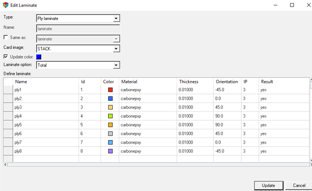
Figure 1.
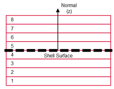
Figure 2.
Sublaminates
Sublaminates define the stacking sequence of ply entities on a portion of a model with complex geometry.
The stack direction for the plies of a sublaminate is defined by an interface definition within an associated interface laminate. Note until the sublaminate is added to an interface laminate, the stack direction is arbitrary.
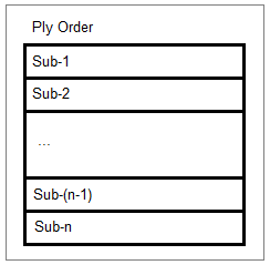
Figure 3.
Interface Laminates
Interface laminates are used to define complex laminated structures that wrap around corners.
Interface laminates specify how the sublaminates of the structure are joined.
The stack direction for the sublaminates of an interface laminate is in the direction of the element's normal. An interface within an interface laminate defines which plies of two sublaminates touch, or interface, with each other. The exact stacking sequence of the plies of the sublaminates is determined by which two plies of the sublaminates are specified in the interface.
Each sublaminate stacked within an interface laminate must have at least one interface definition.
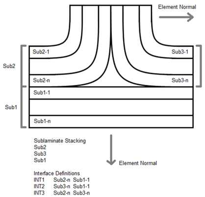
Figure 4.
Supported Solver Cards
Solver cards supported by the laminate entity.
| Solver Card | Laminate Entity |
|---|---|
| Abaqus | None. A template property (*SHELL SECTION COMPOSITE or *SHELL GENERAL SECTION) should be assigned to all elements in composite part. Upon laminate realization, the attributes of the template property are passed to all generated zone properties. The laminate name will populate the LAYUP attribute of each property. |
| ANSYS | None. A template property (SECTYPE SHELL) should be assigned to all elements in a composite part. Upon laminate realization, the attributes of the template property are passed to all generated zone properties. |
| LS-DYNA | None. A template property (*PART COMPOSITE on HyperMesh Component entity) should collect all elements in a composite part. Upon laminate realization, the attributes of the template property are passed to all generated zone properties. |
| Nastran | PCOMPP (Option to realize to PCOMPG or PCOMP). Upon laminate realization, the attributes of the template property are passed to all generated zone properties. |
| OptiStruct | PCOMPP |
| Radioss |
|