CFD-1000: Create a Hybrid Grid Using the CFD Mesh Panel
In this tutorial, you will learn to generate meshes for CFD applications, for example
Fluent and STAR CD using the
CFD Tetramesh panel, generate boundary layer type meshes with an arbitrary number of layers
and thickness distribution, specify/identify boundary regions for CFD simulations, export a
mesh with boundary regions for Fluent, and import the model into
Fluent.
The model file used in this exercise can be found in the es.zip
file. Copy the file(s) from this directory to your working directory.
Load the CFD User Profile
From the menu bar, click Preferences > User Profiles or click the Load User Profile icon,
, on
the Standard toolbar.
Click Engineering Solutions > CFD.
Click OK.
Open the Model File
On the Standard toolbar, click the Open Model
icon.
Select the manifold_surf_mesh.hm file.
Click Open to load the file containing the surface
mesh.
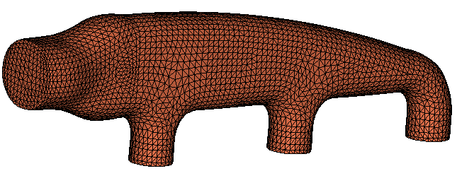
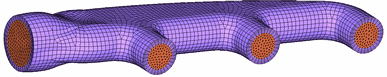
Figure 1.
Inspect the surface elements that will be used to generate the volume
mesh. The boundary mesh can have any combination of tria/quad elements. You will
generate boundary layers on all the surface elements contained in the collector
named wall.
Check That All the Elements in the Collectors Wall, Inlet and Outlets Define a Closed
Volume
Click Mesh > Check > Component > Edges to open the Edges panel.
Click comps and select the collectors
wall, inlet and
outlets.
Click select, and then click find
edges.
A message indicating that no edges were found appears on the status bar.
Toggle free edges to T-connections.
Select the three components again and then click find
edges.
The status bar displays: "No T-connected edges
were found."
Click return to close the panel.
Create the CFD Mesh
Click Mesh > Volume Mesh 3D > CFD Tetramesh to open the CFD Tetramesh panel.
Click the Boundary selection subpanel.
You will need to first select all the elements/components that define the
surface area on which you need to generate boundary layers. This is done by
selecting the elements/components under the With BL (float) and With BL (fixed)
selectors.
Under the heading With BL (fixed), click comps and
select the collector wall. Next, select the remaining
elements/components which define the volume but where a boundary layer is not
desired. This is done by selecting the elements/components under the W/o BL
(float) and W/o BL (fixed) selectors.
Under the heading W/o BL (float), click comps and select
the collectors inlet and
outlets.
Verify that the switch below the W/o BL (float) selector is set to
Remesh.
This means that the meshes in the zones defined by collectors inlet and
outlets will be remeshed after being deformed by the boundary layer growth from
adjacent surface areas.
Select Smooth BL.
This option is strongly recommended for most cases because it produces
boundary layers with more uniform thickness and better element quality.
Click the BL parameters subpanel.
All the data that has been entered in the Boundary selection subpanel is
stored.
Select the options to specify the boundary layer and tetrahedral core: Number
of Layers = 5, First layer thickness =
0.5, BL growth rate = 1.1
(This non-dimensional factor controls the change in layer thickness from one
layer to the next).
Under the BL hexa transition mode header, verify that selection is set to
Simple Pyramid.
The default, Simple Pyramid, uses one pyramid element to transition from a BL
hexahedral’s quad face to the tetrahedral core mesh.
Leave the BL only checkbox unchecked.
This option generates the boundary layer alone and stops before generating the
tetrahedral core. This option modifies adjacent surface meshes to reflect
changes introduced by the boundary layer thickness, and creates a collector
named ^CFD_trias_for_tetramesh, that is used to generate the inner core
tetrahedral mesh using the Tetramesh parameters subpanel.
Click the Tetramesh parameters subpanel.
There are three different tetrameshing algorithms available. Select
Optimize Mesh Quality.
For a detailed explanation of each option, please refer to the online
help.
Set the tetrahedral core growth rate to
Interpolate.
This avoids the problem of generating tetrahedral elements that are too large
at the center of the core mesh.
Click mesh to create the CFD mesh.
When this task is finished, two collectors are automatically created:
CFD_bl001 and CFD_tetcore001. Figure 2.
Click return to close the panel.
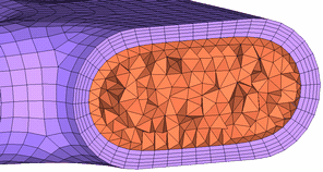
Mask Some of the Mesh to View the Interior Elements and Boundary Layers
You can mask the mesh by using the shortcut key F5, and
select elements to be masked.
The following is a snapshot. Observe the excellent mesh quality produced. Figure 3.
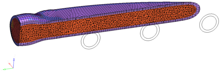
You can also use the Hidden Line panel to view the interior of a solid mesh. ClickBCs > Check > Hidden Lines to access the panel.
Leave the title field blank and check the option for yz
plane.
This defines the yz plane as the cutting plane.
Leave the options for trim planes and clip boundary elements checked on and
click show plot.
This automatically places the cutting plane at the center of the model. Notice
that the display of the elements has been collapsed so that the nodes lie on the
cutting plane. Figure 4.
Left-click in the graphics area where the cutting plane is, hold down the left
mouse button, and drag the mouse.
The cutting plane moves.
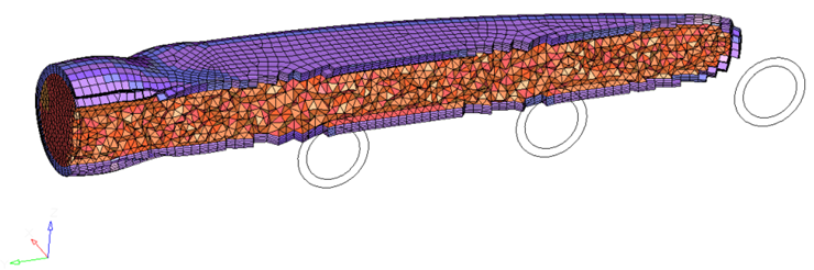
Next, uncheck the option for clip boundary elements and click show
plot.
Notice how the elements are displayed completely.Figure 5.
Drag the placement of the cutting plane. Experiment with the other cutting
planes and the trim planes option to see how they affect the plot.
Click return to exit the panel and clear the plot.
Organize the Model
In this section, you will define mesh surface regions used to specify boundary
conditions in any CFD code, such as Fluent, STAR CD and CFX. For example, assume that you are going to
export the mesh for Fluent. For this model, you need to
create three collectors to place the boundaries: inflow, outflow, and wall. You have
selected two new names that are not already in your database and at the same time
are compatible with the prefixes required by Fluent to
recognize boundary types according to their names.
You are going to reuse the surface mesh contained in collector wall because this mesh
remained unchanged by the CFD mesh process as this component was specified as “fixed
with boundary layer.” However, the surface areas associated with the original
collectors inlet and outlets have been completely regenerated and you need to create
new components that will be named inflow and outflow, respectively.
Using the Model Browser, rename the collector
CFD_tetcore001 to fluid.
This collector will hold all the 3D volume elements.
Click BCs > Organize to move all the elements from the collector CFD_bl001 to
collector fluid.
Click BCs > Faces to automatically generate the collector ^faces containing all the
external faces of the elements in collector fluid.
Click BCs > Components > Single to create two new components named inflow and outflow.
Now you are going to move some of the elements from the collector ^faces to
the collectors inflow and outflow.
In the Model Browser, isolate the
^faces component.
Click BCs > Organize and click one element on the inlet/inflow plane.
The element will become highlighted.
Click elems > by face.
All the elements in the collector ^faces on the inlet/inflow plane will
be selected.
Set the dest comp as inflow, and click
move. Similarly, move the elements from ^faces
associated with the outlets to the collector outflow.
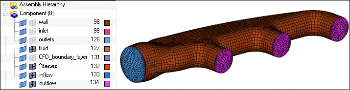
Show the inflow and outflow components in the Model Browser.
When done, you will have all the exterior surfaces colored according to the
collectors where they have been placed, as shown in the following image. Figure 6.
The remaining elements in the collector ^faces are the same as in wall and you
can discard them.
Delete both collectors ^faces and collector CFD_boundary_layer, which is now
empty.
Export Surface and Volume Mesh and Import this Mesh into Fluent
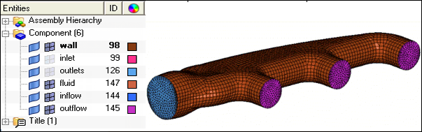
Display only the components containing elements that have to be exported for
Fluent, the components are: fluid, inflow,
outflow and wall. All other components should not be visible.
Figure 7.
Click the Export Solver Deck icon, , to open the Export tab.
Notice that the File Type is set to CFD. Set the Solver Type to
Fluent.
In the File field, click the file icon and specify a name and location for the
file.
Click Export to export the file.
Select Yes to the first message that appears and
No to the second message.
Create a Fluent Simulation Case
If you have access to Fluent, you can import
manifold.cas to create a new Fluent simulation case as follows.
Start Fluent 3d or 3ddp.
From the File menu, select Read, then
Case.
Select manifold.cas.
Click OK.
After importing this file, you will observe that Fluent has recognized the boundary zones outflow, inflow
and wall by name, and the 3D volume zone fluid. Zone interior-* is automatically
created by Fluent containing all the interior faces
shared by two 3D cells.
Select Define, then select Boundary
Conditions.
Select zone inflow, and set the appropriate boundary
condition, such as mass-flow-inlet and velocity inlet.
Change the boundary condition type for the remaining surface zones, outflow and
wall.
Engineering Solutions allows you to perform the most time consuming tasks of
generating the volume mesh and identifying the boundary zones. Now inside
Fluent the rest of the simulation tasks can be
executed easily.
Appendix: Boundary Layer Mesh with Distributed Thickness Ratio
The boundary layer type mesh generated in this tutorial was generated with uniform
thickness. This is OK for a model like this manifold as long as the total boundary layer
thickness does not lead to collision or interference that can occur when the sum of the BL
thickness is close to or larger than the distance separating boundary layer
walls.
When such collision or interference occurs you have the following options:
Decrease the global boundary layer thickness (throughout / for all the BL
surfaces).
Use distributed boundary layer thickness ratios on nodes or
collectors/components. This is a capability in HyperMesh that allows you to specify a local value of
boundary layer thickness by specifying the ratio of the local value to the
global value. For example, if the ratio specified on certain nodes or all
the nodes belonging to a collector is equal to 0.1, then the boundary layer
thickness generated around those nodes will be only 10 percent of the global
boundary layer thickness.
The CFD user profile has a tool (Generate BL Thickness) to generate
automatically “distributed boundary layer thickness ratios” at each node of
the surface mesh so that boundary layer collision is avoided when using the
global or nominal boundary layer thickness. The usage of this tool is
explained in Tutorial CFD-1100.
In this appendix you are going to use option B to manually change the BL thickness
ratio.
Prepare Data to Generate a CFD Mesh (Boundary Layer and Core Mesh) using a Distributed
Boundary Layer Thickness
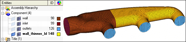
Create a new component named wall_thinner_bl, and move
elements from wall to this new collector, as shown in the following image.
Figure 8.
Click BCs > Check > Edge, then select the collectors wall,
wall_thinner_bl, inlet and
outlets.
Click find edges.
A message indicating that no edges were found appears on the status bar.
Click Mesh > Volume Mesh 3D > CFD tetramesh to open the CFD Tetramesh panel.
Leave the default Smooth BL option unchanged.
In the BL parameters subpanel, select the options to specify the boundary layer
and tetrahedral core: Number of Layers = 5, First layer
thickness = 0.5 and BL growth rate =
1.1.
Select the type of tetrameshing algorithm: Simple Pyramid, Smooth Pyramid, All
Prism or All Tetras.
Ensure the BL only checkbox is not checked.
In the Tetramesh parameters subpanel, set the Pyramid transition ratio =
0.8.
Select the tetrahedral core growth rate switch to
Interpolate.
This avoids the problem of generating tetrahedral elements that are too large
at the center of the core mesh.
Define a Distributed Boundary Layer Thickness on Certain Components
In the BL parameters subpanel, ensure that the BL reduction and Pre calc
checkboxes are checked and click Manual.
The Distributed BL Thickness Ratio dialog opens.
This dialog enables you to specify distributed thickness ratios for groups of
nodes or whole components.
You can choose either Nodes or
Components by selecting the associated radio
button.
Select Components.
Click Select Components and select the component
wall_thinner_bl.
Specify a thickness ratio of value 0.3 and click
Assign.
The summary message now indicates the number of BL thickness ratio loads on
components. When the models are more complex it is useful to display surface
contours of BL thickness ratio values.
Click Contours of BL Thickness Ratio.
The Contour panel automatically displays.
Click contour to inspect the distribution of BL
Thickness Ratio on the surface of your domain.
Click return when you are finished.
Click Close to close the dialog.
Go to the CFD Tetramesh panel, Boundary selection subpanel. Here all the
elements/components that define the surface area on which you need to generate
boundary layers will be selected. This selection is done with the With BL
(fixed) selector.
Click comps under With BL (fixed) and select the
collectors wall and
wall_thinner_bl.
Select all the elements/components that define the surface area on which you do
not want to generate boundary layers. This selection is done with the W/o BL
(float) selector.
Click comps and select the collectors,
inlet and outlets.
The switch below the W/o BL (float) selector is set to Remesh. This means that
the meshes in the zones defined by collector’s inlet and outlets will be
remeshed after being deformed by the boundary layer growth from adjacent surface
areas.
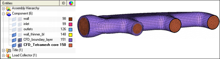
Click mesh to create the CFD mesh.
When this task is finished, note the two collectors automatically
created: CFD_boundary_layer and CFD_Tetramesh_core. Figure 9.
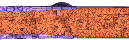
Inspect the relative size of the boundary layer thickness by masking some of
the elements, as shown in the following image. This image shows that the BL
thickness on component wall_thinner_bl is only 30 percent of the global BL
thickness.
Figure 10.
The manual approach followed previously is useful when you need to reduce the
BL thickness throughout a component, or at a clearly identified group of
nodes.
When you have a very complicated geometry and BL collision is likely to
occur, the best approach is to use the Generate BL Thickness tool to
generate automatically “distributed boundary layer thickness ratios” at each
node of the surface mesh. This tool performs a collision study and assigns a
BL thickness ratio to each node of the surface mesh that requires a
reduction of the baseline BL thickness to avoid collision. Usage of this
tool is explained in Tutorial CFD-1100.
The previous steps illustrate simple and effective steps to reduce the BL
thickness on surface components. This approach is very easy to use and
effective when you know how much you want to increase or decrease the BL
thickness all over a component. A similar approach is followed to
increase/decrease BL thickness on groups of nodes.
 , on
the Standard toolbar.
, on
the Standard toolbar.
 icon.
icon.
 , to open the Export tab.