CFD-1500: Use Distributed Thickness for Varying Boundary Layer Thickness
In this tutorial you will learn how to generate a structured quad surface mesh, adjust the boundary layer thickness manually and generate a hybrid grid (tetramesh with boundary layer). You will also export the model for a CFD solver of your choice.
The model file used in this exercise can be found in the es.zip
file. Copy the file(s) from this directory to your working directory.
Load the CFD User Profile
-
From the menu bar, click or click the Load User Profile icon,
 , on
the Standard toolbar.
, on
the Standard toolbar.
- Click .
- Click OK.
Open the Model File
-
On the Standard toolbar, click the Open Model
 icon.
icon.
-
Click Open to load the file.
Generate a Mesh on the Surface
-
Click mesh.
A message on the status bar indicates the number of elements created.
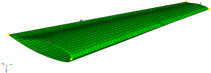
Figure 1.
Adjust the Node Seeding on Each Edge to Get a Structured Quad Mesh
-
Rotate the model and repeat Step 2 for the other end.
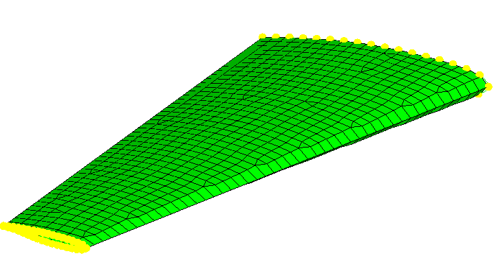
Figure 2.To get a structured quad mesh adjust the number of nodes on the edges in such a way so that two opposite edges have the same number of nodes. See the image below.
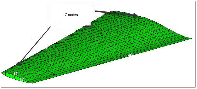
Figure 3. -
Click edge next to adjust and select the edge, as shown
in the image below.
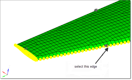
Figure 4. -
Click mesh.
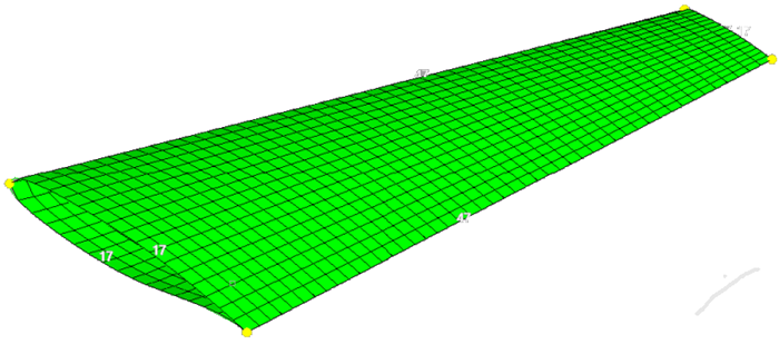
Figure 5.
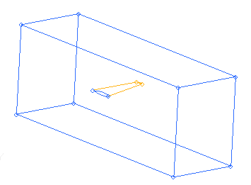
Define the Region for a Thinner BL Thickness
-
Click dest component and select the component
BL_thin.
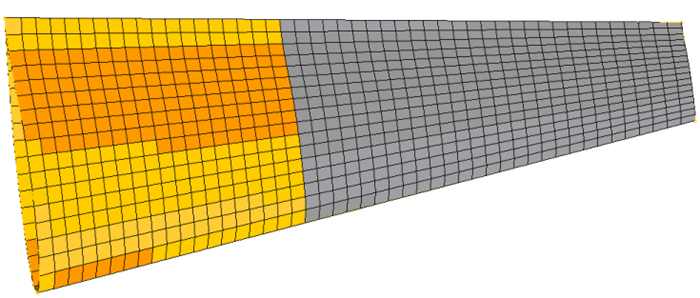
Figure 6.
Mesh the Surface of the Box
- In the Model Browser, turn on the display of the box component, and then press F on the keyboard to fit the model into the graphics region.
- Click and then select the size and bias subpanel.
- With surfs highlighted, select the six surfaces of the box.
- Set the element size field to 30, and change the mesh type toggle to trias.
- Click mesh.
- Double-click return to close the panels.
Volume Meshing
-
Click Assign, and then click
Close.
The defined scaling factor is now stored in the load collector ^CFD_BL_Thickness, as shown in the Model Browser.Note: For all of the nodes in the selected component BL_thin, the boundary layer thickness will be reduced to 1/10 of its initial size. A smooth thickness transition will be used.
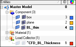
Figure 7. -
In the Model Browser, right-click the
box component and select Hide.
Right-click the load collector ^CFD_BL_Thickness and
select Show. Check the value of the scaling factor to
make sure it is correct and if it is attached to the correct component.
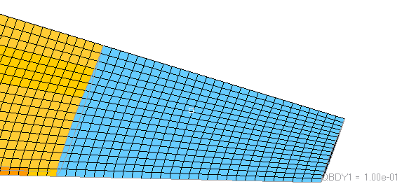
Figure 8. -
To check the result, mask parts of the mesh and compare the thickness of the
boundary layer for the plane component with the thickness of the BL_thin
component. You can do this in the Distance panel. You will see that the
thickness ratio is 1/10, as expected.
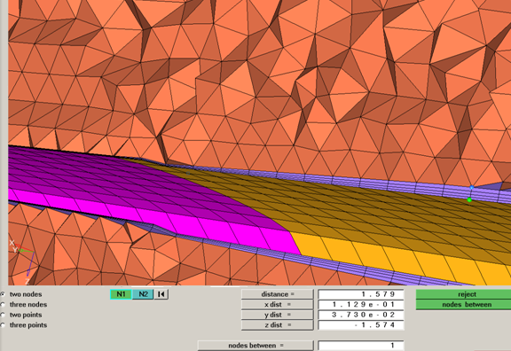
Figure 9.Due to smoothing algorithms for the boundary layer, the thickness ratios can differ from the user-defined values, for some use cases.
Prepare the Model for Export
-
Right-click it and select Isolate.
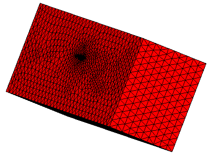
Figure 10. -
Select the elements lying on the inflow boundary, and move them to the inflow
component. The easiest way to do this is to select a single element on the
inflow boundary and then select by face from the extended
entity selector. Repeat this step selecting the elements on the outflow
boundary, and moving them to the outflow component.
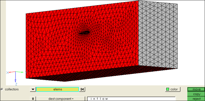
Figure 11.
Export the Model
- Right-click Components in the Model Browser and select Show.
-
Click the
 icon and
export the model for the CFD solver of your choice.
icon and
export the model for the CFD solver of your choice.