OS-T: 1520 Finite Sliding of Rack and Pinion Gear Model
This tutorial outlines the procedure to perform finite sliding analysis on a rack and pinion gear model. The circular gear is called the pinion and it engages teeth on the linear bar called the rack.
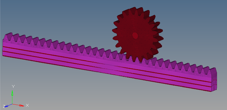
Figure 1. Model Circular Gear and Rack
In small sliding analysis, not only is the relative sliding between main and secondary relatively small but the contact search is done only at the beginning of the simulation. While for finite sliding the contact search is updated for every increment of the analysis. In this case, as you can see, the circular gear has to be in contact with the entire rack over the course of the simulation, so contact status needs to be updated for every increment to capture the entire motion and hence finite sliding is necessary.
This tutorial helps you define finite sliding contact between the circular gear and rack. The gear is held fixed at the center in all dof while the rack is given displacement in x dof but constrained in all other dof. All constraints and enforced displacements have already been defined in model. Contact surfaces to define the secondary and main surfaces are also pre-defined in the model. Contact stabilization has been defined for the contact to help stabilize any rigid body motion before contact gets established. A very tiny end-of-subcase stabilization also has been specified to overcome any temporary instabilities that may sometimes occur at end-of-analysis.
Launch HyperMesh and Set the OptiStruct User Profile
Open the Model
Set Up the Model
Review Material Properties
The imported model contains a large amount of pre-defined information which allows you to focus on the finite sliding section in this tutorial. All material and properties are pre-defined for the circular gear and rack. The material properties of steel are assigned to both components.
-
Verify that the values on the MAT1 Bulk Data Entry for the
material properties of steel are input as shown in Figure 2.
Young's Modulus of Elasticity = 2.1 x 10⁵ N/m2
Poisson's Ratio = 0.3
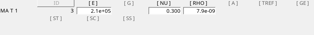
Figure 2.
Review Contact Surfaces and Generate Finite Sliding Contact
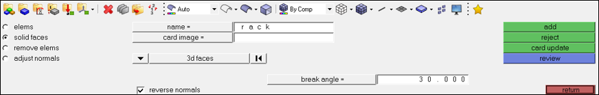
Figure 3. Set Segment Panel
-
Review the contact surface for rack.
- Click name.
- Select rack.
- Click review.
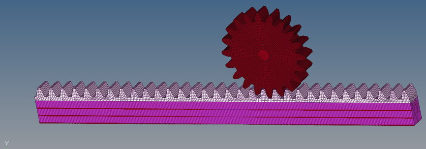
Figure 4. Review of Contact Surface for Rack -
Create a contact surface.
-
Using the set segment selector, select the rack
contact surface for the secondary and the gear
contact surface for the main.
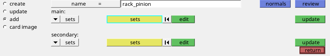
Figure 5. Selecting Main and Secondary Surfaces
-
Using the set segment selector, select the rack
contact surface for the secondary and the gear
contact surface for the main.
-
To review the interface, click review.
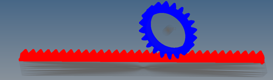
Figure 6. Review interface -
Edit the contact surface.
- Go to the card image subpanel.
- Click edit to edit the contact interface.
- Set TYPE to SLIDE.
- Set DISCRET to S2S.
- Set TRACK to FINITE.
Surface-to-surface a finite sliding contact without friction have been defined.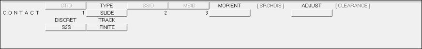 Figure 7. S2S, Finite Sliding Contact Definition
Review Parameters, Contact Output Request and Loadstep Definition
Large displacement formulation needs to be activated for finite sliding contact.
Submit the Job
-
From the Analysis page, click the OptiStruct
panel.

Figure 8. Accessing the OptiStruct Panel
View the Results
-
On the toolbar, click
 (Contour).
-
Under Result type, from the first drop-down menu, select Element
Stresses (2D & 3D)(t).
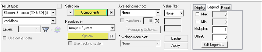 Figure 9. Contour Plot Panel in HyperView
 -
Select Load Factor = 3.369662E-01 and click
Apply.
A contour plot of stresses is created. The load factor here denotes the % of load that has been applied.
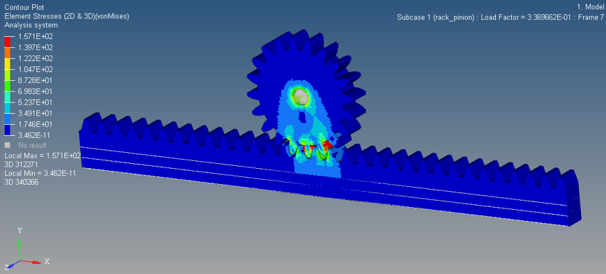
Figure 10. Stress Contour at Load Factor = 3.3696 E-1. The stresses in rack and gear after 33.36% of load has been applied -
Similarly, you can change the load factor and observe the changes in stresses
on the rack and gear.
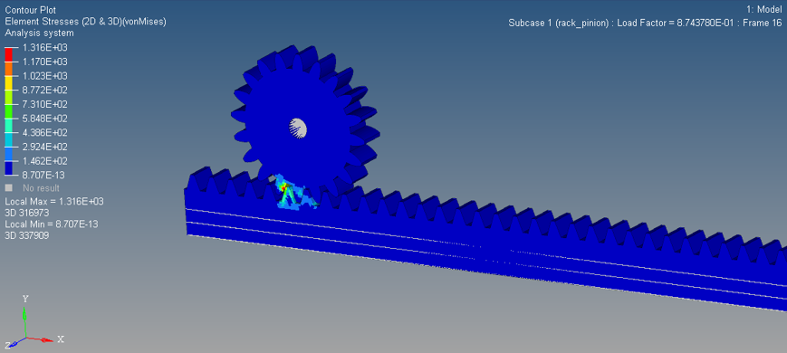
Figure 11. Stress Contour at Load Factor = 8.74E-1. For load factor, if below 0.874, the contact at this point of time is between a very small area of the rack and gear tooth and hence stresses are higher - Optional:
Animate the results using the Set Transient Animation Mode in HyperView.
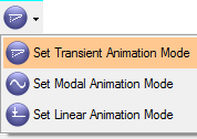
Figure 12.