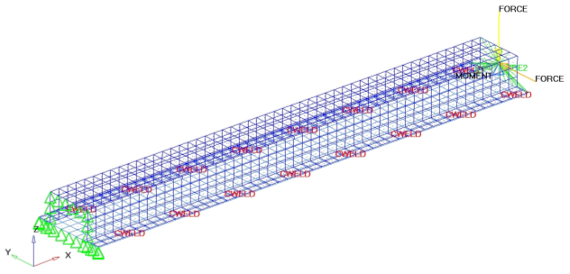
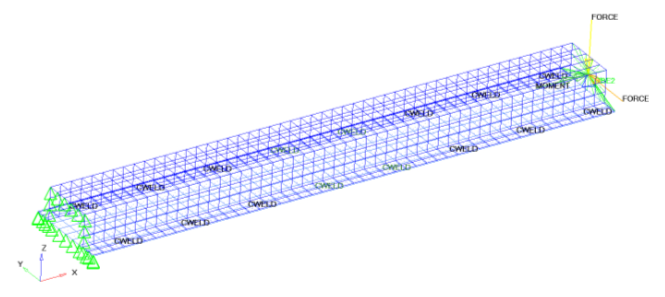
In this tutorial you will perform a 1D topology optimization. The model used in this
tutorial is a simple welded hat section. The welding is modeled using
CWELD elements.
The objective of this tutorial is to minimize the weighted compliance through all
three load cases. The volume fraction of the weld component is limited to 0.3. The
design space is the spot weld component. Figure 1.
Launch HyperMesh and Set the OptiStruct User Profile
Launch HyperMesh.
The User Profile dialog opens.
Select OptiStruct and click
OK.
This loads the user profile. It includes the appropriate template, macro
menu, and import reader, paring down the functionality of HyperMesh to what is relevant for generating models for
OptiStruct.
Open the Model
Click File > Open > Model.
Select the hut.hm file you saved to
your working directory from the optistruct.zip file. Refer
to Access the Model Files.
Click Open.
The hut.hm database is loaded
into the current HyperMesh session, replacing any
existing data.
Set Up the Optimization
Create Topology Design Variables
From the Analysis page, click optimization.
Click topology.
Select the create subpanel.
In the desvar= field, enter tpl.
Set type: to PWELD.
Using the props selector, select PWELD_500.
Click create.
Click return.
Create Optimization Responses
From the Analysis page, click optimization.
Click Responses.
Create the volume fraction response.
In the responses= field, enter Volfrac.
Below response type, select volumefrac.
Set regional selection to by entity and no
regionid.
Using the props selector, select PWELD_500.
Click create.
Create the weighted component response.
In the responses= field, enter wcomp.
Below response type, select weighted comp.
Click loadsteps, then select all
loadsteps.
Change the weighting factors for SUBCASE200 and SUBCASE300 to
100.0.
This increases the influence of the two bending load cases versus the
torsion load case SUBCASE1, which remains at 1.0.
Click return.
Click create.
Click return to go back to the Optimization panel.
Create Design Constraints
Click the dconstraints panel.
In the constraint= field, enter volfrac.
Click response = and select Volfrac.
Check the box next to upper bound, then enter
0.3.
Click create.
Click return to go back to the Optimization panel.
Define the Objective Function
Click the objective panel.
Verify that min is selected.
Click response= and select wcomp.
Click create.
Click return twice to exit the Optimization panel.
Modify Optimization Parameters
To achieve good results, some optimization parameters need to be modified.
Click the opti control subpanel.
Check the box next to DISCRT1D =, then enter
20.0.
This increases the penalty factor in the density method only for the 1D
elements to achieve a discrete result.
Check the check box next to OBJTOL =, then enter
1.e-5.
This reduces the objective tolerance that is checked for convergence.
Click return twice.
Run the Optimization
From the Analysis page, click OptiStruct.
Click save as.
In the Save As dialog, specify location to write the
OptiStruct model file and enter
hut_opt for filename.
For OptiStruct input decks,
.fem is the recommended extension.
Click Save.
The input file field displays the filename and location specified in the
Save As dialog.
Set the export options toggle to all.
Set the run options toggle to optimization.
Set the memory options toggle to memory default.
Click OptiStruct to run the optimization.
The following message appears in the window at the completion of the
job:
OPTIMIZATION HAS CONVERGED.
FEASIBLE DESIGN (ALL CONSTRAINTS SATISFIED).
OptiStruct also reports error messages if any exist. The
file hut_opt.out can be opened in a
text editor to find details regarding any errors. This file is written to the
same directory as the .fem file.
Click Close.
View the Results
In this step you will visualize the new spot weld configuration. To post-process the
results, the weld elements will be sorted by density into different
components.
From the menu bar, click File > Run > Command File.
In the Open Command File dialog, open the
hut_opt.HM.comp.tcl output
file from your OptiStruct run.
Four of the welds are in the DENS 0.9-1.0 component; all others are in
the DENS 0.0-0.1 component.
To do a re-analysis with the new weld configuration, undisplay the components
with low density (DENS 0.0-0.1 to DENS 0.8-0.9) and rerun the analysis with
export options: set to displayed in the OptiStruct panel.