AJ Card
This card uses current data calculated for a PCB as an impressed current source. The data is read from an Altair PollEx .rei file.
On the Source/Load tab, in the Equivalent
sources group, click the ![]() PCB source (AJ) icon.
PCB source (AJ) icon.
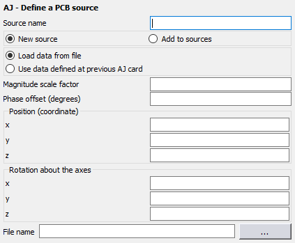
Figure 1. The AJ - Define a PCB source dialog.
Parameters:
- New source
- A new excitation is defined which replaces all previously defined excitations.
- Add to sources
- A new excitation is defined which is added to the previously defined excitations.
- Load data from file
- Read the trace/via currents from a radiated emission interface (.rei) file created with PollEx.
- Use data defined at previous AJ card
- When using multiple AJ cards (different radiating PCBs in the same model) where the current data is identical, it is allowed to load the data just once and at subsequent AJ cards to check this option. The last defined PCB will be used and memory can be saved (no need to store it again). Note that it is still possible to set the PCB position, orientation as well as amplitude and phase individually.
- Magnitude scale factor
- This parameter is used to scale the magnitude of the current values by a constant value.
- Phase offset (degrees)
- This parameter specifies a constant additional phase for the current values in degrees.
- Position (coordinate)
- In this group the X, Y and Z coordinates of the source point (the position where the PCB is located) are entered. These values are affected by the scale factor of the SF card if used.
- Rotation about the axes
- In this group the angles with which the imported PCB is rotated around the X, Y and Z axes are entered in degrees.
- File name
- The name of the PollEx .rei input file.