LF Card
This card impresses a complex impedance between two points inside a FEM mesh.
On the Source/Load tab, in the Loads /
networks group, click the ![]() Load icon. From the drop-down list, click the
Load icon. From the drop-down list, click the ![]() Load FEM (LF) icon.
Load FEM (LF) icon.
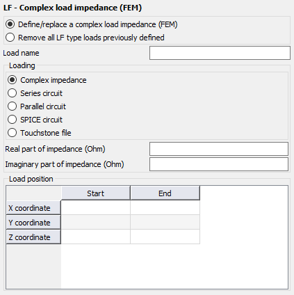
Figure 1. The LF - Complex load impedance (FEM) dialog.
Parameters:
- Define/replace a complex load impedance (FEM)
- Define a load with the following parameters.
- Remove all LF type loads previously defined
- This LF card does not define a load, but rather all previously defined LF loads are deleted. All the other input parameters of this card are ignored.
- Load name
- The name of the load.
- Real part of impedance (Ohm)
- The real part of the complex impedance in .
- Imaginary part of impedance (Ohm)
- The imaginary part of the complex impedance in .
- Complex impedance
- The real and imaginary part of the complex impedance in .
- Series circuit
- The resistor value in , inductor value in Henry and the capacitor value in Farad to be added as a series circuit.
- Parallel circuit
- The resistor value in , inductor value in Henry and the capacitor value in Farad to be added as a parallel circuit.
- SPICE circuit
- Specify the name of an one-port SPICE circuit to define a load between two pins. Define the SPICE circuit using the SC card.
- Touchstone file
- Specify a one-port Touchstone file (.s1p,
.z1p, .y1p) to define a load.Note: If the load is added to a port that has a voltage source, the load is placed in series with the voltage source.
- Load position
- The Cartesian coordinates of the start and end points of the load.
The complex impedance is impressed between two points inside the FEM mesh. The line may be positioned arbitrarily inside the FEM mesh, meaning it does not have to be coincident with tetrahedral edges, but the length between the points should be small compared to the shortest wavelength in the band of interest to obtain reasonable accuracy.
Note: The LF type load should not be used to model a short-circuit load. A short can be
modelled by a metallic strip (meshed into triangles) inside a FEM region.