NW Card
This card defines a linear non-radiating network.
On the Source/Load tab, in the Loads /
networks group, click the ![]() General network (NW) icon.
General network (NW) icon.
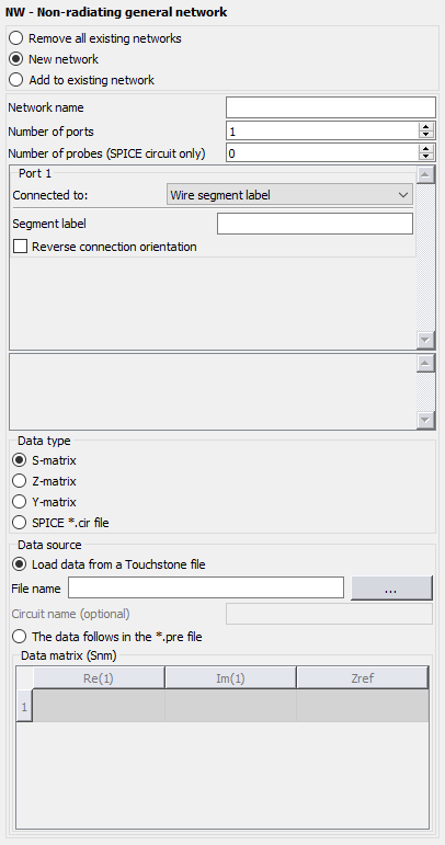
Figure 1. The NW - Non-radiating general network dialog.
Parameters:
- Remove all existing networks
- All previously defined non-radiating networks are removed
- New network
- A new non-radiating network is created after removing all previously defined networks.
- Add to existing network
- A non-radiating network is created and added to any previously defined networks.
- Network name
- The name of the network.
- Number of ports
- A network can consist of any number of ports, but is required to have at least one port.
- Number of probes (SPICE circuit only):
- The number of current/voltage probes to be added to the network. A choice is given between a Voltage probe and a Current probe. The Probe name is the name of the defined probe.
- Port n
- Each port of a network can be connected to other network ports or geometry. Note that the orientation of a network port connection can easily be reversed for all connections except if connected to internal ports.
- Data type
- The network data can be specified with S-parameters, Z-parameters, Y-parameters or a SPICE .cir file.
- Load data from Touchstone file
- The network data can be loaded from a Touchstone file (in v1.1 format). The data in a Touchstone file is always defined in increasing order and at specific frequencies only. These may of course not directly coincide with the frequencies at which the Feko kernel is run. The solution is to interpolate both the magnitude and phase data by using cubic spline interpolation. The Feko frequency is considered out of bounds when it is more than 0.1% away from the lowest/highest frequency defined in the Touchstone file. In such an instance an error will be given and Feko will terminate. If the Feko frequency is within bounds, but not between points, no interpolation will be performed.
- Load data from a SPICE file
- A passive circuit network can be loaded from a SPICE file.
- Absolute port reference
- A .cir file is to be supplied containing the required SPICE circuit description. This description should include a sub-circuit definition (..SUBCKT subnam N1 <N2 N3 ..>) with its name identical to the current NW card name. Its external number of ports should also agree in number with the number of ports defined for this NW card.
- Relative port reference
- A .cir file is to be supplied containing the required SPICE circuit description. This description should include a sub-circuit definition (..SUBCKT subnam N1p N1m <N2p N2m N3p N3m ..>) with its name identical to the current NW card name. Its external number of ports should be double the number of ports defined for this NW card.
- Circuit name (optional)
- The sub-circuit name may be specified for SPICE networks.
- The data follows in the *.pre file
- For small networks with four ports or less, the network matrix can be inserted directly in the .pre file. The matrix is entered as real and imaginary components. S-parameters also require a real reference impedance to be specified for each port.
Connection Guidelines
Note the following guidelines regarding the connections between network ports:
- It is not necessary to specify all possible connections. If, for example, NWName1.Port1 is specified as connected to NWName2.Port1, it is not necessary to specify the reverse, that is the connection from NWName2.Port1 to NWName1.Port1. You should ensure that sufficient information is available to link all connected ports.
- If an internal port should be left open, then no connection should be entered.