Browsers supply a great deal of view-related functionality by listing the parts of a model in a tabular and/or tree-based
format, and providing controls inside the table that allow you to alter the display of model parts.
FE geometry is topology on top of mesh, meaning CAD and mesh exist as a single entity. The purpose of FE geometry
is to add vertices, edges, surfaces, and solids on FE models which have no CAD geometry.
Tools and workflows that are dedicated to rapidly creating new parts for specific use cases, or amending existing
parts. The current capabilities are focused on stiffening parts.
Create and edit systems, assemblies, and analyses, use wizards to build models quickly, create and edit belt/pullies,
NLFE stabars, and NLFE springs, access the EDEM and Track Builder tools.
Create and edit points, bodies, lines (curve graphics), solids (graphics), markers and vectors, edit grounded/ungrounded
bodies, create and edit rigid body groups, configure gravity, and select material properties.
Use the Points tool to create and edit
individual points, points on a vector, points along a curve, points at
the center of a circle, and parametric points.
Use the tool to create curve graphics from a set of selected
points or nodes. The generated curve graphics can be used to setup 2D
rigid to rigid contact or advanced joints, such as point to curve or
curve to curve joints. Based on the selected set of points or nodes
belonging to a file graphic or CAD graphic, this tool creates a 3D
cartesian curve and a curve graphic.
There are three ways in which a box graphic (or cuboid) can be defined based on the location of the graphic reference
frame about which the graphic is being created. The dimensions for the graphic are also specified using this reference
frame.
A curve graphic is created by positioning a 3D curve entity (Cartesian or parametric curve) in a reference frame (marker).
The reference frame can be an explicit marker or can be implicitly defined using a body-point-orientation method.
A graphic system entity acts similar to that of a general system entity - it is intended to be used as a container
for graphic entities, and it can be used repetitively. Like general systems, graphic systems can use attachments that
refer to entities that are external to the system - this allows you to use them repetitively by parameterizing the
body, point, etc. that are typically needed to define the graphics within the graphic system.
Create and edit outputs, create and edit templates, run the solver, view reports, access the Load Export utility,
use the Optimization Wizard, open HyperStudy, utilize many pre-processing and post-processing capabilities with regards
to flexible bodies (or flexbodies), run MS/EDEM cosimulation in batch mode, and generate H3D from EDEM.
Create and edit points, bodies, lines (curve graphics), solids (graphics), markers and vectors, edit grounded/ungrounded
bodies, create and edit rigid body groups, configure gravity, and select material properties.
There are three ways in which a box graphic (or cuboid) can be defined based on the location of the graphic reference
frame about which the graphic is being created. The dimensions for the graphic are also specified using this reference
frame.
There are three ways in which a box graphic (or cuboid) can be defined based on the
location of the graphic reference frame about which the graphic is being created. The
dimensions for the graphic are also specified using this reference frame.
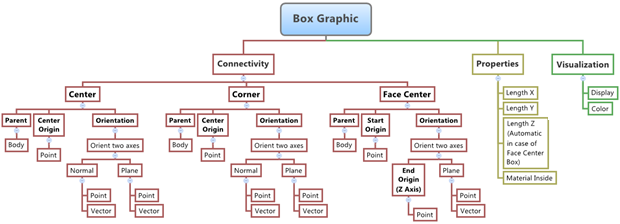
The figure below shows the various box graphic options and settings that are
available in MotionView: Figure 1.
If the Graphics panel is not currently displayed, select the desired graphic by
clicking on it in the Project Browser or in the modeling window.
The Graphics panel is automatically displayed.
From the Connectivity tab, use the Type drop-down menu to select a type for the
box graphic.
Option
Description
Center
The center box graphic has its origin of the reference frame about
which the box is defined located at the geometrical center of the
box.
Corner
The corner box graphic has the origin of the reference frame located
at any one of the eight corners of the box.
Face Center
The face center box graphic has its origin located at the center of
one of the faces.
Note: If the selected graphic is a pair entity, first distinguish between the
Left and Right tabs in the
panel, and then edit the properties. When defining a pair graphic, use pair
entities for Body, Origin, etc.
Click the Body collector and
select a body from the modeling window, or double click
the Body collector to open the Model Tree (from which the desired body can be selected).
Click the Point
collector (under Origin) and select a point from the modeling window, or double click the
Point collector to open the Model Tree (from which the desired point can be selected).
Use the orientation options to orient the
coordinate system.
Define the graphic properties.
Click the Properties tab.
Enter the dimensions of the box graphic by providing values for
LengthX, LengthY, and LengthZ.
In the case of a face center box, LengthZ is automatically determined
by the distance between the origin and reference point for the Z axis
(the two points that define the Z axis of the reference frame).
Select the material property to be associated with the graphic.
Tip:
Activating the Material inside check box sets
the normals such that the graphic will act like a solid object. For
contacts outside of the box, activate on this option. If the contact
is to be detected from inside the box, deactivate this option.
The refinement level sets the mesh
coarseness level for HyperWorks. HyperWorks will use a tessellation scheme to
represent the graphic object during solution. Refer to the <Post_GraphicMotionSolve statement for additional
information.
Click the Inertia Properties
tab and review the mass and center of mass coordinates for the graphic.