From the Post ribbon, click the Displacement
tool. Figure 1.
The tool contains the following:
Entity Set
Define one or more sets
Properties
Shows all properties of the selected sets
loadcases
List of subcases available inside all of the imported result files
FBD Plot and Display
Visualization options
The workflow is:
Create a set
Set the properties of a selected set
Select a loadcase
Set the options of the free-body plot
Plot free-body displacements and rotations for the selected loadcase
Create a Set
To create a set, right-click and select Create.
Set Properties of a Selected Set
Select a set.
The properties display.
Name
The name of the selected set.
ID
The ID of the selected set.
Card Image
This property is optional. Defines the card for the set.
Entity IDs
Available if None has been defined as Card Image, and non-ordered or
ordered as Set Type. Select what nodes and elements will belong to
the set. If an element set has been selected, the free-body
displacement will use all nodes belonging to the selected
elements.
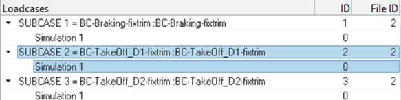
Select a Loadcase
Select a loadcase to plot free-body displacements and rotations.
Figure 2.
Free-Body Plot and Display
Define visualization options for the free-body plot.
FBD Plot: Resolve In
Selects the coordinate system to plot free-body displacements and rotations.
Options vary depending on the solver.
FBD Plot: System
Available if a user-defined system has been selected.
Selects the coordinate system to plot free-body displacements and
rotations.
FBD Plot: Tolerance
Displacements and rotations with an absolute value lower than the tolerance
are not displayed.
FBD Plot: Translation
Defines what displacement component will display.
FBD Plot: Rotation
Defines what rotation component will display.
FBD Plot: Show values
Defines if free-body vector values will display.
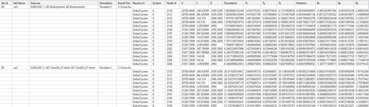
FBD Plot: Summary table
Creates tables with free-body displacements and rotations for the selected
sets and loadcases. Figure 3. Figure 4.
FBD Plot: Load Creation
Creates an include file where free-body displacements and rotations are
properly realized as loads (enforced displacements) for that model for
selected sections and selected loadcases.
FBD Plot: Create Fields
Creates field entities with free-body displacements and rotations for the
selected sets and selected loadcases.
Display: Size Scaling
Defines how free-body vectors will be scaled for visualization.
Display: Arrow Length (%)
Scales free-body vectors for visualization.
Display: Color
Change the color of each force or moment component.
Display: Vector Heads
Defines if the free-body vector points to the node or out of it.
Display: Vector Style
Change the style of free-body vectors.
Display: Numeric Format
Defines what free-body vector values will be displayed in fixed or
scientific format.
Defines the amount of decimal places.
Plot Free-Body Displacements and Rotations
Plot free-body displacements and rotations for the selected loadcase.
On the FBD Plot tab, click Apply to show
free-body vectors.