FBD Forces
Calculate the contribution of one or more elements to the force and moment equilibrium at desired nodes.
Figure 1.
- Free Body Sections
- Define one or more cross-sections or groups of elements
- Properties
- Shows all properties of the selected free-body section
- Loadcases
- The loadcases available inside all of the imported result files
- FBD Plot and Display
- Visualization options
Free-body sections can be defined by selecting explicitly a group of elements and (optionally) which nodes of this group to be considered for the contribution of forces and moments (standard section type). They can also be defined using a cutting plane, which defines a dynamic cross-section. In this case all of the elements intersected by this plane will be considered as defining such cross-section, while the nodes belonging to these elements at one or another side of the plane will be considered for the calculation. It is possible to realize a cross-section type into a standard one.
- Create or import free-body sections
- Set the properties of a selected free-body section
- Select a loadcase
- Set the options of the free-body plot
- Plot free-body forces and moments for the selected loadcase
Create or Import Free-Body Sections
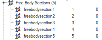
Figure 2.
Set Properties of a Selected Free-Body Section
Select a Loadcase
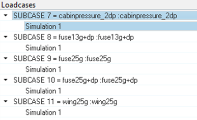
Figure 3.
FBD Plot and Display
Define visualization options for the free-body plot.
- Free body forces/moments
- Defines whether free-body forces and moments must be shown at each boundary
node or at all nodes. If the section group is made up only by elements and
the node ID list is empty, the boundary nodes option searches for all of the
nodes that are shared with the rest of the model.
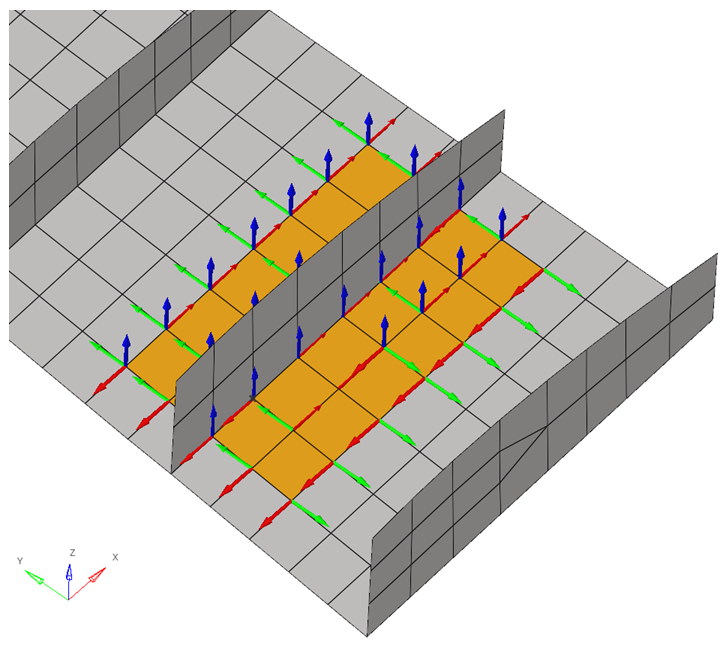
Figure 4. All Nodes Option
Figure 5. Boundary Nodes
Figure 6. Boundary Nodes - Resultant forces/moments
- Defines that free-body forces and moments must be shown at the summation point that is defined. If more than one option is selected, forces and moments are summed up.
- Cross Section Position
- Moves the cross-section plane along its normal direction within the boundaries of the model. If the cross-section is realized, this option will not be available.
- Flip
- Allows you to select nodes that are on the opposite side of the
cross-section’s plane normal. If the cross-section is realized, this option
will not be available.
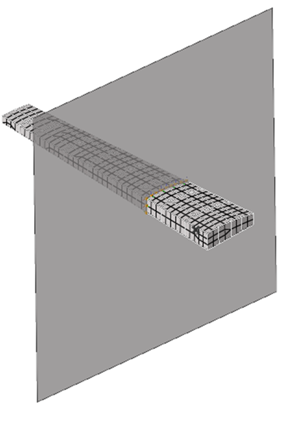
Figure 7.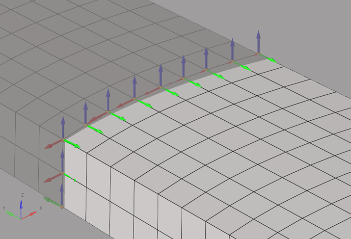
Figure 8.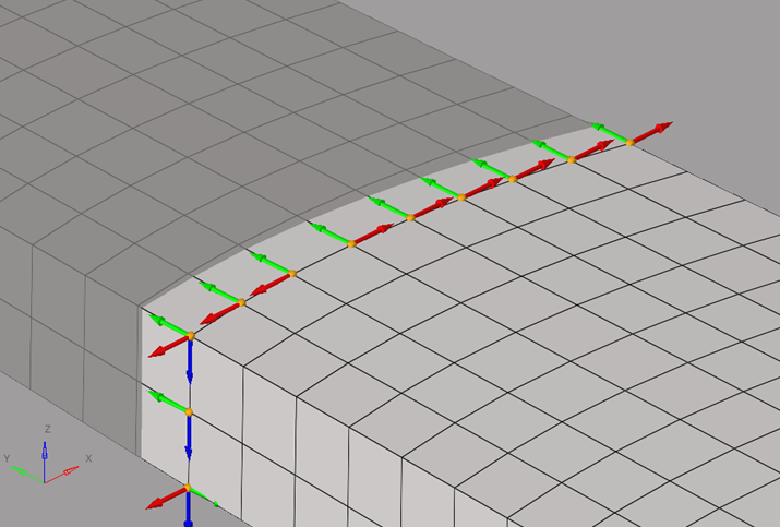
Figure 9. - Tables
- Creates tables with free-body forces and moments for one or multiple sections and for one or multiple loadcases. The summary table (and summary table summation points) can be used to create Potato/VMT plots.
- The summary table shows all forces and moments for nodes and summation
points.
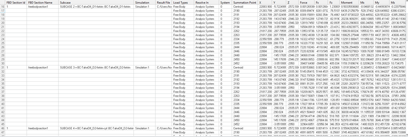
Figure 10. - The summary table summation points show all forces and moments at summation
points only.
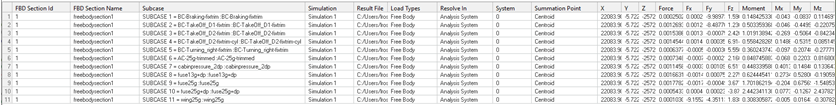
Figure 11. - The min/max table shows the higher and lower values of forces and moments at
summation points among the selected loadcases.

Figure 12. - Load Creation
- Creates an include file, where free-body forces and moments are properly realized as loads for that model for selected sections and selected loadcases.
- Resolve In
- Defines the coordinate system in which the loads will be created. Options vary depending on the solver.
- Include Name
- Defines the name of the include file in which the loads will be exported.
- Forces
- Selects force components to be exported.
- Moments
- Selects moment components to be exported.
- Create Fields
- Create field entities with free-body forces and moments for the selected sections and selected loadcases.
- Load Types
- Select what type of free-body data must be shown. Options vary depending on the solver. If more than one option is selected, values at the same location are summed up.
- Tolerance
- Forces or moments with an absolute value lower than the tolerance are not displayed.
- Forces
- Defines which force components will display.
- Moments
- Defines which moment components will display.
- Show Values
- Defines if free-body vector values will display.
- Size Scaling
- Defines how free-body vectors will be scaled for visualization.
- Arrow Length (%)
- Scales free-body vectors for visualization.
- Color
- Change the color of each force or moment component.
- Vector Heads
- Defines if the free-body vector points to the node or out of it.
- Vector Style
- Change the style of free-body vectors.
- Numeric Format
- Defines if free-body vector values should be displayed in fixed or scientific format. It also defines the amount of decimal places.
Plot Free-Body Forces and Moments
Plot free-body forces and moments for the selected loadcase.
- On the FBD Plot tab, click Apply to show free-body vectors.
- On the FBD Plot tab, click Clear to hide vectors.
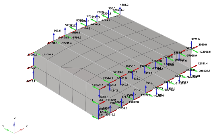
Figure 13.
Free Body CSV File
The FBD Forces tool can import or export one or more cross-sections using the .csv file format.

Figure 14.

Figure 15. Displayed in a Calculation Sheet Software
- Section Name
- The free-body section's name.
- Section Color
- The free-body section's color.
- Section Type
- Defines the type of the free-body section. The standard type corresponds to a realized cross-section. The cross-section type has not been realized. Therefore, you can change the cross-section position.
- Element List
- Defines a list of elements for the standard type or the coordinates of a base point for the cross-section type.
- NodeList/Normal
- Defines a list of nodes for the standard type or the coordinates of a point for the cross section type. This point, together with the base point defined on Element List/Normal, will establish a normal vector.
- SumPointType
- Defines where forces and moments will be summed up.
- SumPointValue
- If the summation point is at the centroid it must be left empty.
- ResolvedInSystem
- Defines which coordinate forces and moments should be plotted.
- SystemId
- If the ResolvedInSystem System is the analysis or global system, it must store 0.
Nastran’s Monitor Points 3
The FBD Forces tool can export one or more cross-sections using Nastran’s Monitor Point 3 Format (.bdf file).
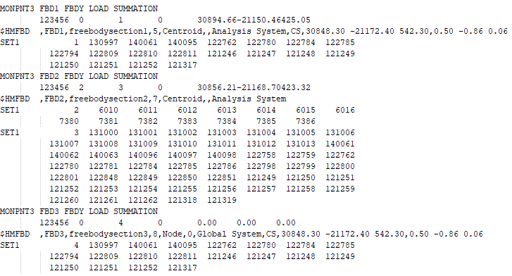
Figure 16.