Composite Browser
Use the Composite Browser to create, organize, and manage composite modeling data.
The Composite Browser consolidates entities and tools used in ply-based models. Ply-based models can be created, edited and reviewed from within the Composite Browser. Additionally, composite stress toolbox functionality, such as ABD matrix calculation, is provided in the context menu of relevant entities.
Browser Interface
The Composite Browser interface.
- The top pane contains a hierarchical view of either ply-based, or zone-based composite data.
- The bottom pane contains the Entity Editor.
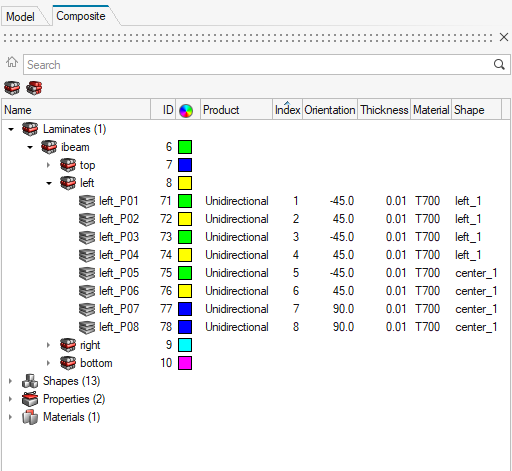
Figure 1.
Views
Composite views.
View options appear at the top of the Composite Browser.
Laminate View
- Laminates
- Plies
- Shapes (sets)
- Properties
- Materials
- System Collectors
- Tables
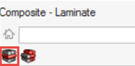
Figure 2.
- Plies can be dragged between the Unstacked Plies folder and the laminate in which they should be stacked.
- Ply order within a laminate can be manipulated by dragging one of more plies to a new location within the laminate.
- Interface Laminates and sublaminates can be defined by dragging one or more laminates into another laminate. The parent becomes an interface laminate and the children become sublaminates. For more information on this modeling technique, see Interface Laminates.
- Material, Ply and Laminate level composite stress toolbox calculations, accessed from the Analyze context menu option.
Zone View
- Laminate level composite stress toolbox calculations, such as ABD matrix calculation, accessed from the Analyze context menu option.
- Editing of orientation, thickness and material of plies passing through a zone. Any changes will propagate to all zones that contain the edited ply.
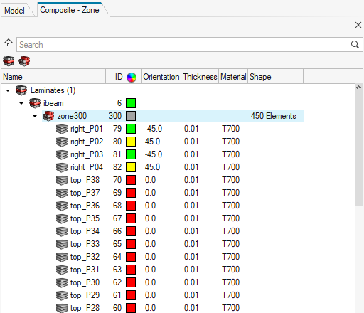
Figure 3.
Orientation Visualization
Common orientation methods.
Figure 4.
- Ply 1 Direction: Displays ply 1 direction (fiber) orientations. If a drape table is assigned to the selected ply, drape corrections are included as part of the vector.
- Material Reference: Displays the x, y and z axes of the material reference orientation. This is the direction which ply orientations rotate from.
Composite Stress Toolbox
Composite stress tools functionality.
- Laminates: If plies have a shape defined by an element set, all zones of contain thickness in laminate. If one or more plies do not have shape defined, the full list of plies in the laminate is used.
- Zones
- Plies
- Materials
Additionally, analysis entities can be created to run laminate strength, load response, and first ply failure analyses. For more information, see Composite Stress Toolbox.
Solver-Specific Details
Details for various solvers.
Entities created in the Composite Browser are assigned the most common solver card for a typical ply-based model. Properties and Shapes are filtered based on solver card to only display appropriate cards for a ply-based model. Additionally, in the OptiStruct profile, the appropriate card is set for laminate and ply entities upon creation.
OptiStruct
| Entity | Displayed Cards |
|---|---|
| Property | PCOMPP |
| Set | SET_ELEM, None |
Radioss
| Entity | Displayed Cards |
|---|---|
| Property | PCOMPP |
| Set | SET_ELEM, None |
Abaqus
| Entity | Displayed Cards |
|---|---|
| Property | *SHELL_SECTION_COMPOSITE, with “Defined layers” unchecked |
| Set | ELSET, None |
ANSYS
| Entity | Displayed Cards |
|---|---|
| Property | SECTYPE, with TYPE=SHELL, PLIES=0 |
| Set | SET_ELEM, None |
LS-DYNA
| Entity | Displayed Cards |
|---|---|
| Property | SectShll |
| Set | Shell, None |
Nastran
| Entity | Displayed Cards |
|---|---|
| Property | PCOMPP |
| Set | SET, None |
Context Menu
Access additional composite options from the Composite Browser's context menu.
Utilities
Tools for working with composites.
FE Absorb Plies
FE Absorb Plies generates a ply-based model from zone-based properties.
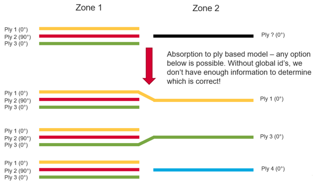
Figure 5.
-
Import zone-based models with zone-based solver properties.
These FE models do not have any plies or laminates. The goal is to create plies and laminates from the zone-based solver properties.
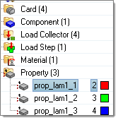
Figure 6. No Plies or Laminates are in the FE Model -
If a zone ply shape has multiple disconnected regions, generate multiple plies,
one for each disconnected region, by selecting Split disconnected ply
regions into separate new ply entities.
After the conversion, laminates and plies are created. However converting a zone-based model to a ply-based model is not deterministic if global IDs or names are not defined in the properties. Many possibilities exist, especially the laminate stacking order. You are advised to check the laminate and reorder, if necessary.
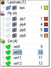
Figure 7. Ply, Laminate and PCOMPP are Created in the Model after FE Absorb
Material Orientation
The Material Orientation tool provides several methods of assigning material x directions for shell and solid elements, and additionally z directions for solid elements.
- Select the Entities on which to assign material orientation, either Elements or Properties.
- Set the Color of orientation vectors drawn after applying material orientation.
- To set the scale of orientation vectors drawn after applying material orientation, set Scaling Option to Auto or Manual.
- Type a value into the Size field for the manual input for size of orientation vectors drawn after applying material orientation.
- Set the X direction method. Choose from the following:
- Curve – spatially map input curve(s) as the x direction
- Lines/Edges – lines which define the orientation
- Flip direction – for lines/edges only. Determines whether the curve provided is +x direction or -x direction.
- Nodes – list of lines that define the orientation
- System ID – system assigned as orientation
- System Axis – system and axis of system to map as x direction
- Angle – for OptiStruct and Nastran only. Directly enter rotation applied on THETA field of element.
- Curve – spatially map input curve(s) as the x direction
- Set a value for Normal by choosing one of the following:
- Element Normal – uses element z direction (can be viewed from panel if elements are selected). Typically, this option should be used.
- Surface Normal – aligns material z direction spatially to selected surface.
By Curve
- Select the elements for which a new material angle will be assigned.
- Select the lines or list of nodes to define the material direction. The
element centroid will be taken and projected to the closest line/node
segments and the line tangent direction will be found to assign the material
angle.
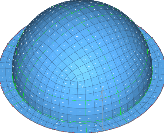
Figure 8. A Circular Pattern of the Material Orientation is Assigned Based on the Outer Circular Line Direction
Other material orientation tools are also available.
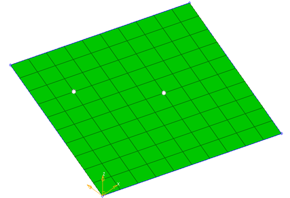
Figure 9. Two Nodes are Selected for Material Direction
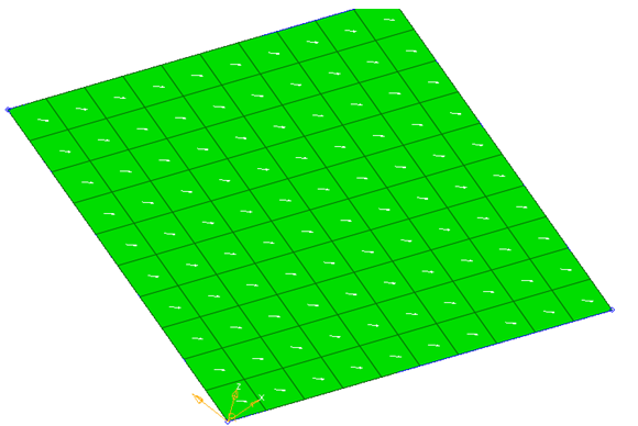
Figure 10. Material Direction in the Same Direction as two Nodes
By System ID
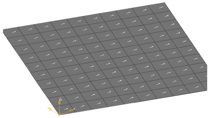
Figure 11. X Axis of the System is used for Projection
By System Axis
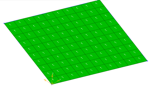
Figure 12. System Local Axis 2 is Projected to Create Material System
By Angle
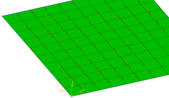
Figure 13. Element N1-N2 Direction
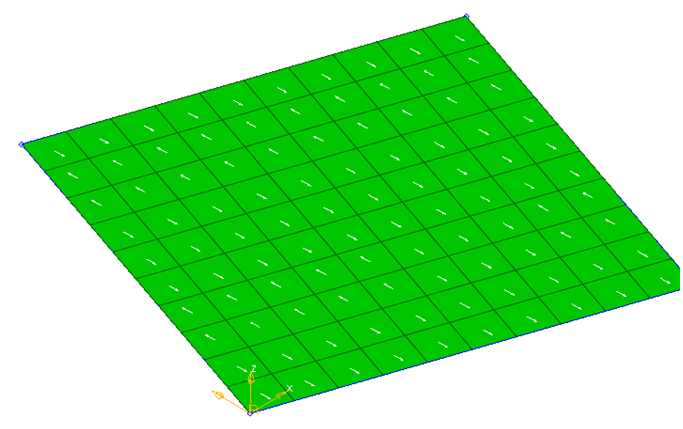
Figure 14. Material System is Created at an Angle to N1/N2 Direction
Ply Geometry Smoothing
Ply Geometry Smoothing provides functionality to smooth finite element ply shapes, usually generated from concept level composite freesize optimization, and to generate geometry from finite element ply shapes.
-
Provide the step file name.
Geometry plies are created and exported to step files.
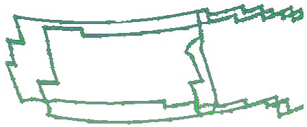
Figure 15. Result of Smoothing with Iterations = 0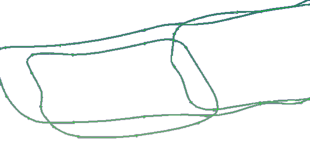
Figure 16. Result of Smoothing with Iterations = 20
Ply Rename
Ply Rename provides several automated ply renaming methods
-
Specify Digits to pad the Index or ID with “0” characters to the left. This
input is the total number of digits in the string
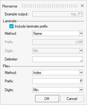
Figure 17.