/FAIL/HASHIN
Block Format Keyword Describes the Hashin failure model. This failure model is available for Shell and Solid.
Format
| (1) | (2) | (3) | (4) | (5) | (6) | (7) | (8) | (9) | (10) |
|---|---|---|---|---|---|---|---|---|---|
| /FAIL/HASHIN/mat_ID/unit_ID | |||||||||
| Iform | Ifail_sh | Ifail_so | ratio | I_Dam | Imod | I_frwave | |||
| Sdel | Tcut | ||||||||
| (1) | (2) | (3) | (4) | (5) | (6) | (7) | (8) | (9) | (10) |
|---|---|---|---|---|---|---|---|---|---|
| Soft | |||||||||
| (1) | (2) | (3) | (4) | (5) | (6) | (7) | (8) | (9) | (10) |
|---|---|---|---|---|---|---|---|---|---|
| fail_ID |
Definition
| Field | Contents | SI Unit Example |
|---|---|---|
| mat_ID | Material identifier (Integer, maximum 10 digits) |
|
| unit_ID | Unit Identifier (Integer, maximum 10 digits) |
|
| Iform | Formulation flag.
(Integer) |
|
| Ifail_sh | Shell failure flag.
(Integer) |
|
| Ifail_so | Solid failure flag.
(Integer) |
|
| ratio | For
Isolid=2 or
Ifail_sh=2: the
element will be deleted, if more than ratio of the layers (or integration points)
have failed. Default = 1.0 (Real) |
|
| I_Dam | Damage calculation flag. 6
(Integer) |
|
| Imod | Relaxation time calculation.
(Integer) |
|
| I_frwave | Failure propagation flag between neighbor elements.
(Integer) |
|
| Low strain rate limit. Default = 0.0 (Real) |
||
| Longitudinal tensile strength (in fiber direction). Default = 1020 (Real) |
||
| Transverse tensile strength (perpendicular to the fiber direction). Default = 1020 (Real) |
||
| Through thickness tensile strength. Default = 1020 (Real) |
||
| Longitudinal compressive strength (in fiber direction). Default = 1020 (Real) |
||
| Transverse compressive strength (perpendicular to the fiber direction). Default = 1020 (Real) |
||
| Crush strength. Default = 1020 (Real) |
||
| Fiber shear strength. Default = 1020 (Real) |
||
| Matrix shear strength 12. Default = 1020 (Real) |
||
| Matrix shear strength 23. Default = 1020 (Real) |
||
| Matrix shear strength 13. Default = 1020 (Real) |
||
| Coulomb friction Angle for matrix and
delamination < 90 degrees. Default = 0 (Real) |
||
| Sdel | Delamination criteria scale factor. Default = 1.0 (Real) |
|
| Dynamic time relaxation. 5 Default = 1020 (Real) |
||
| Reference strain rate. Default = 10-20 (Real) |
||
| Tcut | Strain rate cutoff period. Default = (Real) |
|
| Soft | Reduction factor applied to failure criteria when
one of neighbor elements has already
failed. Only used if, I_frwave=2. 0.0. ≤ Soft ≤ 1.0 Default = 0.0 (Real) |
|
| fail_ID | (Optional) Failure criteria identifer. 4 (Integer, maximum 10 digits) |
Example (Composite)
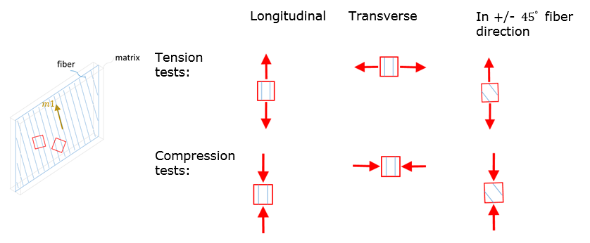
Figure 1. Fabric Lamina Model (Iform =2)
#RADIOSS STARTER
/UNIT/1
unit for mat and failure
#              MUNIT               LUNIT               TUNIT
                  kg                  mm                  ms
#---1----|----2----|----3----|----4----|----5----|----6----|----7----|----8----|----9----|---10----|
/MAT/COMPSH/1/1
composite material
#              RHO_I
              1.5E-6
#                E11                 E22                NU12     Iform                           E33
                  42                  40                 .05         1                            .5
#                G12                 G23                 G31              EPS_f1              EPS_f2
                 3.4                   3                   3                   0                   0
#             EPS_t1              EPS_m1              EPS_t2              EPS_m2                dmax
                   0                   0                   0                   0               .9999
#              Wpmax               Wpref      Ioff    IFLAWP               ratio
                   0                   0         5         0                   0
#                  c          EPS_rate_0               alpha                              ICC_global
                   0                2E-4                   0                                       1
#            sig_1yt                b_1t                n_1t           sig_1maxt                c_1t
                  .1                  25                  .1                   0                   0
#            EPS_1t1             EPS_2t1          SIGMA_rst1            Wpmax_t1
                   0                   0                   0                   0
#            sig_2yt                b_2t                n_2t           sig_2maxt                c_2t
                  .1                  20                  .1                   0                   0
#            EPS_1t2             EPS_2t2            sig_rst2            Wpmax_t2
                   0                   0                   0                   0
#            sig_1yc                b_1c                n_1c           sig_1maxc                c_1c
                .005                 800                  .5                   0                   0
#            EPS_1c1             EPS_2c1            sig_rsc1            Wpmax_c1
                 .08                 .15                  .1                   0
#            sig_2yc                b_2c                n_2c           sig_2maxc                c_2c
                .005                2000                  .5                   0                   0
#            EPS_1c2             EPS_2c2            sig_rsc2            Wpmax_c2
                   0                   0                   0                   0
#           sig_12yt               b_12t               n_12t          sig_12maxt               c_12t
                .004                  83                 .31                   0                   0
#           EPS_1t12            EPS_2t12           sig_rst12           Wpmax_t12
                .075                .085                 .05                   0
#          GAMMA_ini           GAMMA_max               d3max
                1E31                1E31               .9999
#  Fsmooth                Fcut
         0                   0
#---1----|----2----|----3----|----4----|----5----|----6----|----7----|----8----|----9----|---10----|
/FAIL/HASHIN/1/1
#    Iform  Ifail_sh  Ifail_so               Ratio     I_Dam      Imod   Ifrwave         EPS_DOT_MIN
         2         1         0                   0         1
#           Sigma1_T            Sigma2_T            Sigma3_T            Sigma1_C            Sigma2_C
                   2                .525                1E30                 1.7                 1.7
#            Sigma_C           SigmaF_12           SigmaM_12           SigmaM_23           SigmaM_13
                1E30                1E30                .075                1E30                1E30
#                Phi              Sdelam             Tau_max           EPS_DOT_0                Tcut
                   0                   1                 .01
#---1----|----2----|----3----|----4----|----5----|----6----|----7----|----8----|----9----|---10----|
#enddata
#---1----|----2----|----3----|----4----|----5----|----6----|----7----|----8----|----9----|---10----|
Comments
- Example of ratio: if ratio=0.5, and Ifail_sh=2 (or Ifail_so=2), the element will be deleted, if more than half of the layers (or integration points) failed.
- The 3D material failure model:
- Uni-directional lamina model:Tensile/shear fiber mode:
(1) Compression fiber mode:(2) with,
Crush mode:(3) with,
Failure matrix mode:(4) Delamination mode:(5) Where,
Note:(6) - Fabric lamina model:Tensile/shear fiber mode:
(7) (8) With
Compression fiber mode:(9) with,(10) with,
Crush mode:(11) with,
Shear failure matrix mode:(12) Matrix failure mode:(13) Where,
If the damage parameter is Fi ≥ 1.0, the stresses are decreased by using an exponential function to avoid numerical instabilities. A relaxation technique is used by decreasing the stress gradually:(14) With,(15) and
Where,- Time
- Start time of relaxation when the damage criteria is assumed
- Time of dynamic relaxation
- Stress at the beginning of damage
- Uni-directional lamina model:
- The damage value, D is 0 ≤ D ≤ 1. The
status for fracture is:
- Free, if 0 ≤ D > 1
- Failure, if D=1
with for uni-directional lamina model and for fabric lamina model. This damage value shows with /ANIM/BRICK/DAMA or /ANIM/SHELL/DAMA.
- The fail_ID is used with /STATE/BRICK/FAIL and /INIBRI/FAIL. There is no default value. If the line is blank, no value will be output for failure model variables in the /INIBRI/FAIL (written in .sta file with /STATE/BRICK/FAIL option).
- After the failure criterion is reached, the value determines a period of time when the stress in the failed element is gradually reduced to zero. When the stress reaches 1% of the stress value at the start of failure, the element is deleted. This is necessary to avoid instabilities coming from a sudden element deletion and a failure “chain reaction” in the neighboring elements. Even if the failure criterion is reached, the default value of results in no element deletion. Therefore, it is recommended to define 10 times larger than the simulation time step.
- The I_Dam option improves damage calculation and stability calculating damage.