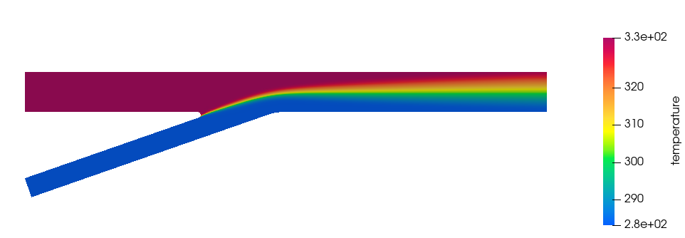
ACU-T: 4200 Humidity – Pipe Junction
Prerequisites
This tutorial provides the instructions for setting up and running a basic transient humidity transport simulation using a pipe junction model. Prior to starting this tutorial, you should have already run through the introductory tutorial, ACU-T: 1000 Basic Flow Set Up, and have a basic understanding of HyperWorks CFD and AcuSolve. To run this simulation, you will need access to a licensed version of HyperWorks CFD and AcuSolve.
Prior to running through this tutorial, click here to download the tutorial models. Extract ACU-T4200_Humidity.hm from HyperWorksCFD_tutorial_inputs.zip.
Problem Description
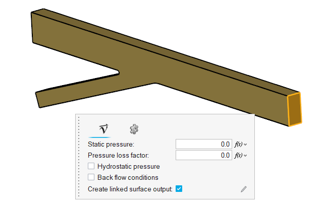
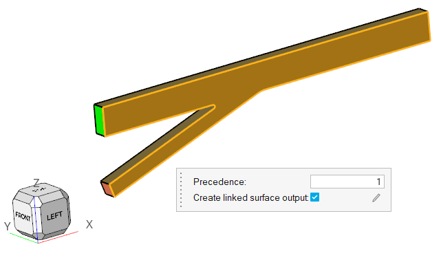
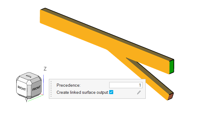
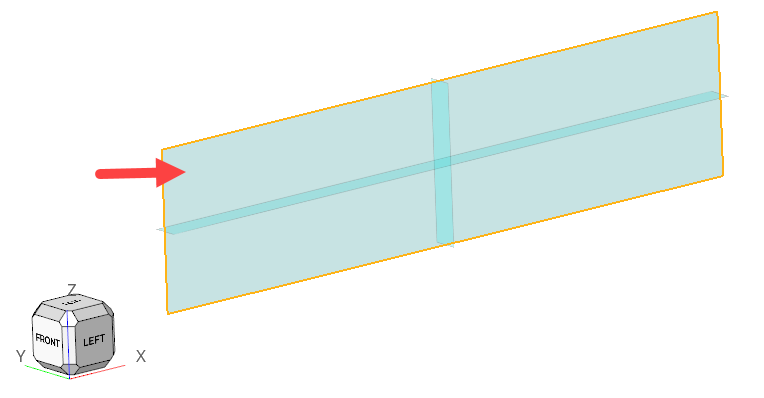
The problem to be addressed in this tutorial is shown schematically in Figure 1. As an example, a pipe junction problem is attached here to show the capability of the Humidity modelling in AcuSolve. In this problem, there are two inlets with different flow, thermal, and humidity conditions. As the flow proceeds downstream of the pipe, two pipes merge into a single pipe to create a single outlet and a distinct profile of temperature and humidity is attained. The geometry is symmetric about the XZ midplane of the pipe, as shown in the figure.
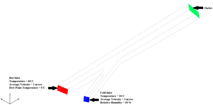
Figure 1.
Start HyperWorks CFD and Open the HyperMesh Database
Validate the Geometry
The Validate tool scans through the entire model, performs checks on the surfaces and solids, and flags any defects in the geometry, such as free edges, closed shells, intersections, duplicates, and slivers.

Figure 3.
Set Up Flow
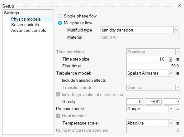
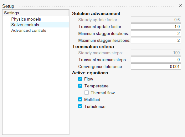
Set Up the Simulation Parameters and Solver Settings
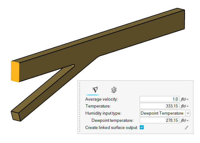
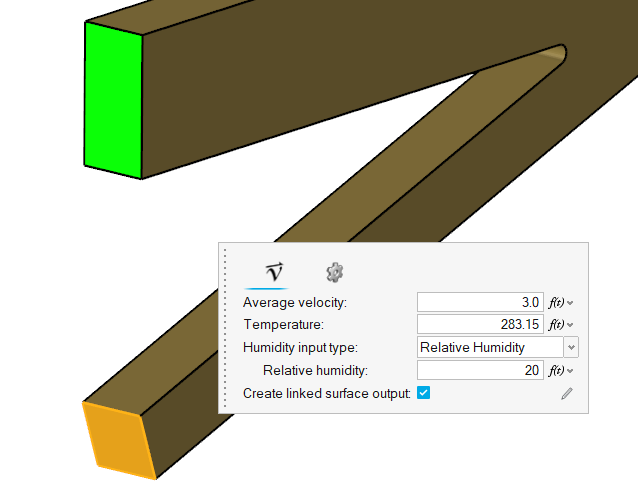
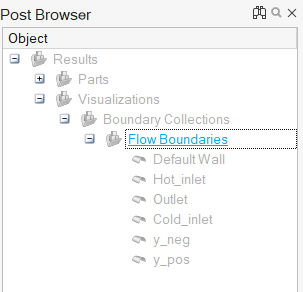
Define Flow Boundary Conditions
Compute the Solution
The input HyperMesh database contains the mesh, hence you do not need to generate the mesh again.
Define the Nodal Initial Conditions
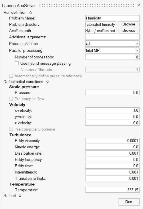
Run AcuSolve
Post-Process the Results with HW-CFD Post
In this step, you will create contour plots for temperature, relative humidity, mass fraction humidity, and velocity.
Summary
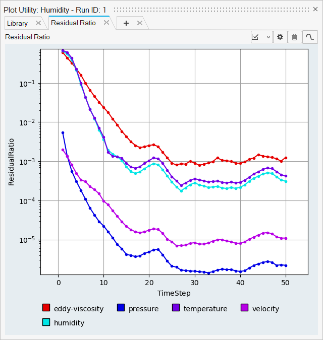
In this tutorial, you learned how to set up and solve a humidity transport simulation using HyperWorks CFD and AcuSolve. You started by importing the HyperWorks CFD input database and then defined the flow setup. Once the solution was computed, you created a plot of residual ratios using the plot utility in HyperWorks CFD. Finally, you created a contour plot of temperature distribution, relative humidity, humidity mass fraction, and velocity using HyperWorks CFD Post.


