FE Geometry
FE geometry is topology on top of mesh, meaning CAD and mesh exist as a single entity. The purpose of FE geometry is to add vertices, edges, surfaces, and solids on FE models which have no CAD geometry.
Tools and workflows operate similarly on CAD as they do with FE. With FE geometry, mesh selections are made easier as they are topology-based.
FE geometry can be used for 1D and 2D elements. It is recommended to use FE geometry where there is no associated CAD.
FE Geometry Creation
FE geometry creation in HyperWorks tools is controlled from .
When the create mode is set to CAD geometry, all points, lines, surfaces, and solids created will be CAD geometry.
When the create mode is set to FE geometry, all points, lines, surfaces, and solids created will be FE geometry.
Midmesh default extraction output will be FE geometry only.
Creation Rules Applied in Tools and Workflows
- For CAD geometry inputs, expected output is CAD geometry.Ruled surface creation from two CAD edges gives CAD geometry surface.
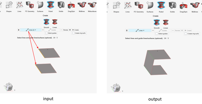
Figure 1. - For FE geometry inputs, expected output is FE geometry.Ruled surface creation from two FE geometry edges gives FE geometry surface.
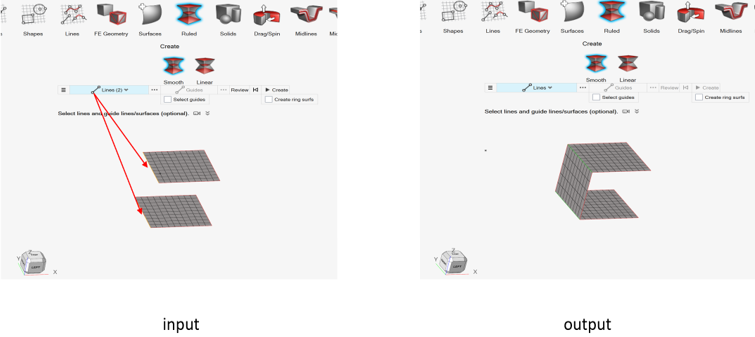
Figure 2. - For mixed inputs (CAD geometry + Fe geometry), expected output is CAD
geometry.Ruled surface creation from mixed selection (CAD edge and FE geometry edge), gives CAD surface.
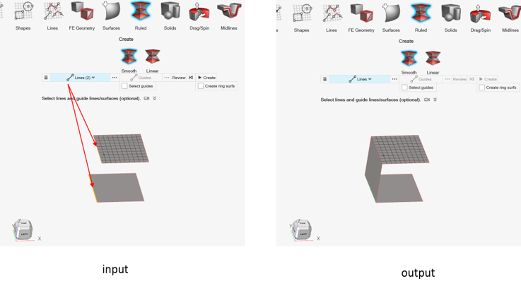
Figure 3.
FE Topology Revision
FE topology revision in HyperWorks tools is controlled from .
Any of the three methods can be used for FE topology revision.
- Keep mesh
- Keep existing mesh on FE topology revision.
- Remesh
- Remesh surrounding mesh on FE topology revision.
- Rebuild
- Rebuild surrounding mesh on FE topology revision.
- Number of layers
- Define the zone to be remeshed or rebuild on topology revision.
Convert To and Update FE Geometry
Use the FE Geometry tools to convert elements or CAD surfaces into FE geometry, or update existing FE geometry.
-
From the Geometry ribbon, click the FE
Geometry tool.

Figure 4. -
Select an option from the secondary ribbon.
Option Description From CAD 
Select CAD geometry with associated elements to convert. From Elements 
Select elements that are not associated with geometry to convert. Click
 on the guide bar
to define options.
on the guide bar
to define options.- Create at features
- Simple - Fast method of identifying features based solely on the angle between normals of adjacent elements. Based on this, the surface is created.
-

Figure 5. - Edge feature angle
- Feature angle based on angle between normals of adjacent element normals. Based on the settings, features are created on the surfaces.
- Vertex feature angle
- Maintain connectivity of the input surfaces to any attached surfaces.
- Allow open features
- Orphan feature edges can be created with this option, as shown in Figure 5 by the Simple example.
- Create at component boundaries
- Feature edge separating the component boundary is created while creating different surfaces.
- Create solids
- Orphan elements forming an enclosed volume are converted into a solid.
- Create at 1D elements
- Feature edges are created at 1D elements.
Update 
Select existing FE geometry to update. Surfaces and elements can be selected, and, using the options above, new FE geometry can be created.
In addition to the "From Elements" options, click
on the guide bar
to define:- Remove existing features
- Before creating FE geometry, existing features can be removed.
- Create at selection boundaries
- Feature edges are created considering element selection.
FE Geometry Visualization
- The CAD icon from the browsers turns on/off both geometry and mesh.
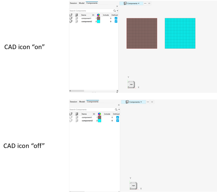
Figure 6.Note: The FE icon in the browser does not have any effect on FE geometry. - Show all elements will show FE geometry.
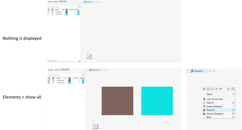
Figure 7. - Hiding partial elements from an FE geometry surface will hide all elements
of that FE geometry surface.
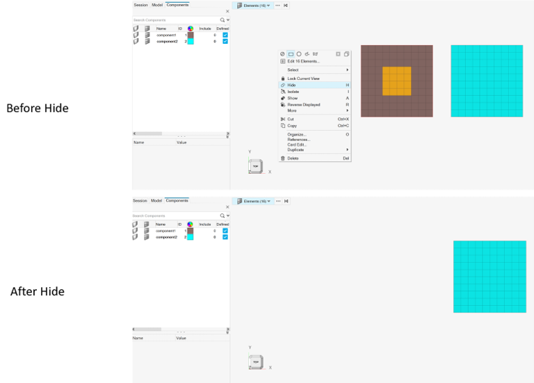
Figure 8. - Isolating partial elements from an FE geometry surface will isolate all
elements of that FE geometry surface.
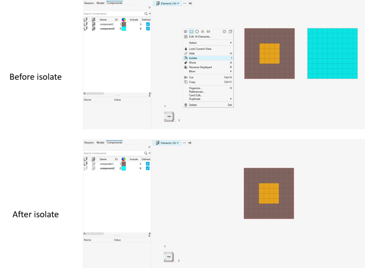
Figure 9. - Hiding partial 1D elements from an FE geometry line will hide all elements
of that FE geometry line.
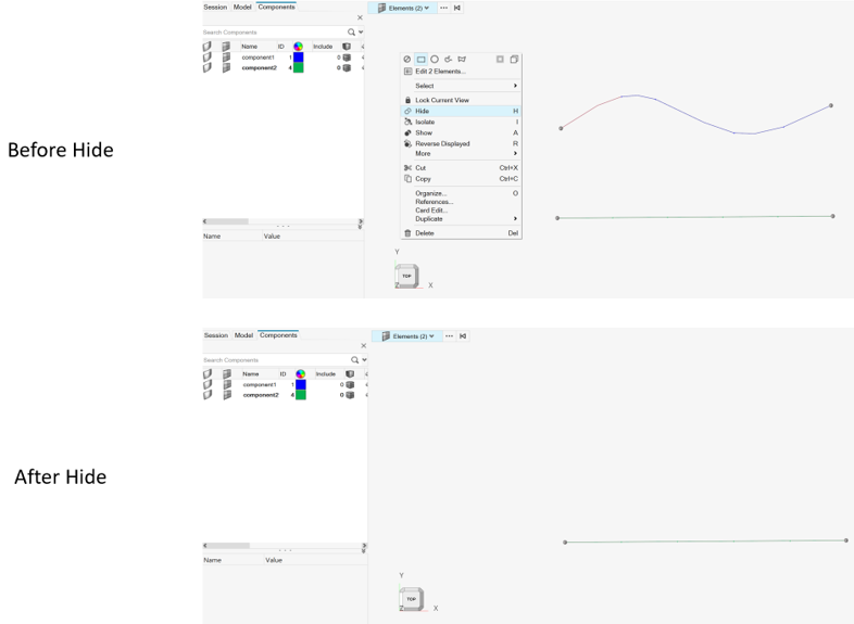
Figure 10. - Isolating partial elements from an FE geometry line will isolate all
elements of that FE geometry line.
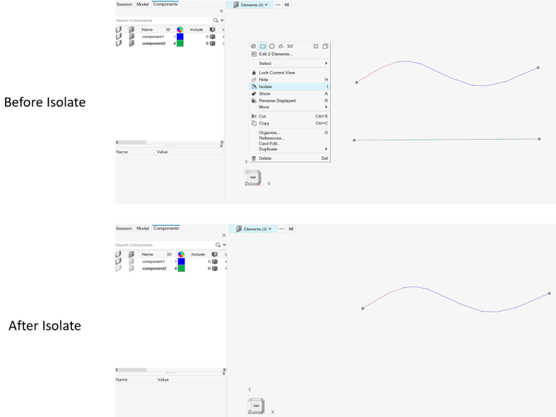
Figure 11. - Hiding partial elements from an FE geometry solid will not have any
visualization effect.

Figure 12. - Isolating partial elements from an FE geometry solid will isolate all
elements of that FE geometry solid.
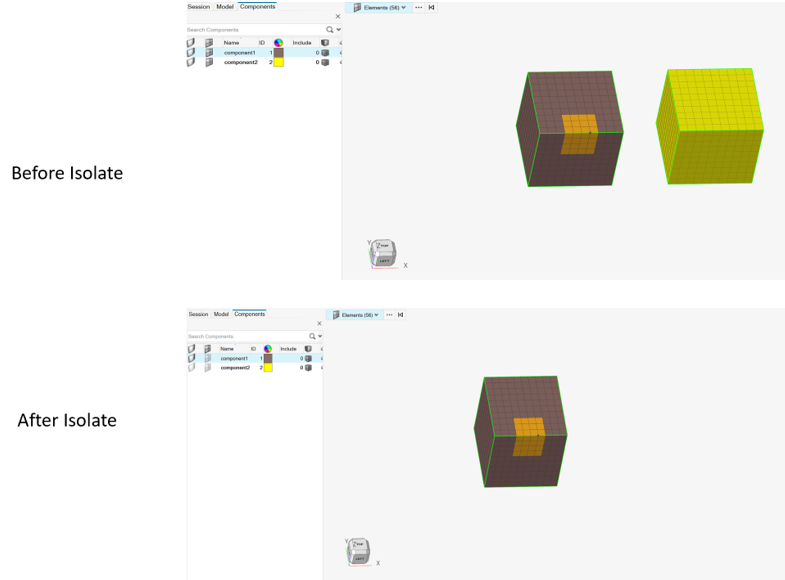
Figure 13. - Elements of FE geometry organized in different component collectors can be
visualized in FE component mode only.
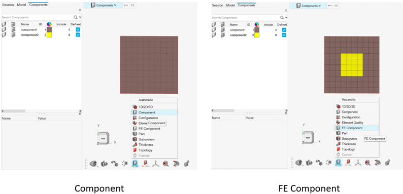
Figure 14.Note:- Visualizing by component shows FE geometry surface component color.
- Visualizing by FE component shows FE geometry element component color.
- Organizing an FE geometry surface to a new component will move all its
surface elements to that component.
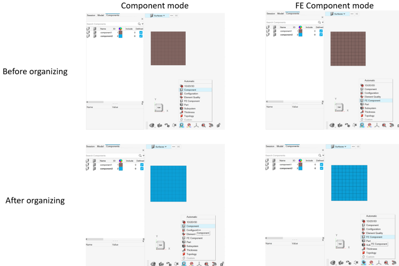
Figure 15.Note: The surface and its elements belong to the same component.- Recommendation:
- It is suggested to keep FE geometry surfaces and their elements in the same component. However, in some cases like map thickness, elements can be organized in different components.
Functionalities Without FE Geometry Support
Below is a list of functionalities not yet supporting FE geometry in HyperWorks 2022
Geometry
- Extend: Stitch at target using “Auto trim intersecting surface” option is not supported.
- Cross Extend
- Offset
- Ruled: Mixed selection of CAD and FE geometry surfaces is not supported.
- Drag/Spin: Preview of FE geometry solid is not available.
- Midlines: FE geometry solid is not supported
- Midsurfaces
- Split > Lines: FE geometry line split is not supported.
- Split > Surfaces: Extend trimmer is not supported for FE geometry.
- Split > Surfaces: “Trim both” is not supported for mixed selection.
- Split > Surfaces: “Self-intersecting surfaces” is not supported for mixed selection.
- Split > Surfaces: Split CAD using FE geometry is not supported.
- Split > Plane: FE geometry line split is not supported.
- Split > Plane: Review is not available for FE geometry solid split.
- Stitch: Mixed selection is not supported.
- Suppress: Mixed selection is not supported.
- Unsuppress
- Fillets
- Boolean
- Plug
- Defeature > Cuts, Small Features, Logos, Fillets and Batch
- Preserve Edges
Mesh
- Batchmesh and Rigid body meshing does not support FE geometry as input.
- Assign plot contour is not supported for FE geometry elements in the Check elements (F10) 1D & 2D panel.
- Tetra: FE geometry solid elements creation is not supported.
- Hex: FE geometry solid elements creation is not supported.
- Solid Map: FE geometry solid elements creation is not supported
- Thin Solids: FE geometry solid elements creation is not supported.
Elements
- Refine > Auto quads and Box
- Coarsen
- Imprint/Extend
- Hole/Gap Fill
- Normals: Display and adjust normals for FE geometry surface is not supported.
HyperMesh Post
HyperMesh post-processing does not support FE geometry.
If a solver deck is imported with the Create FE geometry option "on", or a portion of the model is converted to FE geometry, HyperMesh post functionalities are lost. You need to delete the FE geometry present in the model before proceeding to HyperMesh post-processing.