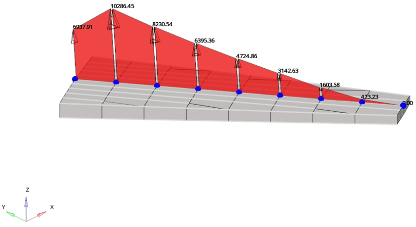
FBD Trace Plot
Display free-body forces and moments at each cross-section along a node path.

図 1.
- FBD Section Group
- Define one or more cross-section groups.
- Properties
- Shows all properties of a selected FBD section group
- Loadcases
- List of subcases available inside all imported result files
- Trace Plot and Display
- Visualization options
- Create a FBD section group
- Set the properties of the selected cross-section group
- Select a loadcase
- Set the options for the trace plot
- Display the trace plot for the selected loadcase
フリーボディ断面の作成
- Name
- FBD断面グループの名前。
- Select Node Path
- FBD断面グループの節点パスを選択します。
- Select Intersect Entity
- FBD断面グループの節点パスに沿った目的の要素を選択します。FBD Forcesツール上の断面では、プレーンと交差しているすべての要素が使用されます。ただし、Trace Plotツールを使用すると、考慮する要素を指定できます。
- Number of cuts between nodes
- 選択された各ペアの節点間の追加断面の量を定義します。
- Cutting plane definition
- Trace Plotツールによって作成されたすべての断面の法線方向を定義します。
- Direction
- このオプションを使用できるのは、切断面の定義が共通方向に設定されている場合です。すべての断面の法線方向として使用されるベクトルを定義します。
- System definition
- 結果を評価するために使用される座標系を定義します。
すべてのFBD断面グループはModelブラウザに表示されます。
選択したFBD断面グループのプロパティの設定
- Name
- FBD断面グループの名前。
- ID
- FBD断面グループのID。
- Color
- FBD断面グループの色。
- Intersect entity ids
- FBD断面グループの節点パス沿いの目的の要素を選択します。
- System definition
- 結果をプロットするために使用される座標系を定義します。
- System
- このオプションを使用できるのは、座標系定義がUser definedに設定されている場合です。結果をプロットするための座標系を選択します。
- Orientation Vector
- このオプションを使用できるのは、座標系定義がDirection basedに設定されている場合です。XY面を定義するための方向ベクトルを定義します。
荷重ケースの選択

図 2.
トレースプロットの表示オプション
トレースプロットの表示オプションを定義します。
- Load Types
- 表示する必要のあるフリーボディデータのタイプを選択します。
- Tolerance
- トレランスを下回る絶対値を持つ力やモーメントは表示されません。
- Force/Moment
- 表示する力またはモーメント成分を定義します。
- Arrow Length (%)
- トレースプロットをスケーリングして表示します。
- Numeric format
- トレースプロットの値を、固定小数点と浮動小数点のどちらのフォーマットで表示するのかを定義します。小数点以下の桁数も定義します。
- Plot Direction
- トレースプロットの方向を選択します。
- Sum At
- 力とモーメントが合計される場所として重心または節点を選択します。
- Display At
- 力とモーメントが表示される場所として重心または節点を選択します。
- Show values
- トレースプロットの値を表示するには、このオプションを選択します。
Display the Trace Plot for the Selected Loadcase
- Click Apply to show the trace plot.
- Click Clear to hide the trace plot.

図 3.