EG Card
The EG card indicates the end of the geometrical input. It is essential that the EG card is used.
On the Home tab, in the Structure group,
click the ![]() End geometry (EG) icon.
End geometry (EG) icon.
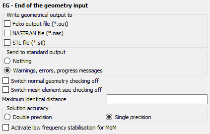
Figure 1. The EG - End of the geometry input dialog
Parameters:
- Write geometrical output to
- The geometry data of the segments and surface elements can be written to the Feko output file, a NASTRAN format file, an STL file, or any combination thereof. The name of the NASTRAN or STL file will be the same as the Feko model, but with a .nas or .stl extension. Writing the geometry data to the output file may lead to huge output files.
- Send to standard output
- If the field Nothing is selected, no messages are sent to the standard output device (usually the screen). If the item Warnings, errors, progress messages is selected, warnings, errors and messages that indicate the program’s progress are sent to the standard output device.
- Switch normal geometry checking off
- If this item is checked, the verification of the geometry elements Feko will be switched off (see the discussion below this table).
- Switch mesh element size checking off
- If this item is checked, the verification of the mesh elements size in relation to the frequency will be switched off
- Solution accuracy
- This parameter can be set to force Feko to use single precision for the storage of the memory critical arrays. Single precision storage is the default behaviour, and as compared to double precision the memory requirement is then half. Using double precision is recommended when the Feko kernel gives a warning to switch to double precision (this might happen for instance at low frequencies where an increased accuracy is required).
- Activate low frequency stabilisation for MoM
- If this item is checked, low frequency stabilisation for MoM is activated.
The following should be noted regarding the export of the Feko geometry to NASTRAN or STL:
- The STL export just dumps the data of all triangular patches of the Feko model to an ASCII formatted STL file. Any other geometry (for example wires, tetrahedra) is not exported since the STL format does not make provision for this. It should also be noted that the Feko mesh does not contain any information about the geometry that the triangle mesh elements were created from. Thus there is no special grouping of elements based on regions or solid parts in the STL file. This implies that the exported STL file does not represent a valid STL file in the strict sense. However, the exported information is still useful in most cases.
- For the NASTRAN export, the wide column format is used to ensure that all significant digits are exported. Unlike the STL export, in NASTRAN all the various mesh elements used in Feko are present. However, information is lost, for instance for wire elements the thickness (wire radius) can not be exported simply because the NASTRAN file format does not make provision for this. Also the NASTRAN property is used to represent the Feko label. But since NASTRAN properties are just integer values and the Feko label can be an arbitrary string, a mapping is done so that from each Feko label just the associated number is used and exported as the NASTRAN property.
The Maximum identical distance is used to set the tolerance in the mesh. The mesh information is created by the program PREFEKO, and stored in a .pre file, in which all the triangles and segments are described by their corner points. Due to rounding errors it is possible that, for example, end points of connecting segments do not coincide. When searching for nodes, an ohmic connection is made when the difference is smaller than the Maximum identical distance.
Feko automatically checks for typical user errors that have been observed in the past. Examples of errors are connecting a wire segment to the middle of another wire, where the connection points do not coincide, or connecting surfaces that have different segmentation along the common edge. Such errors are detected if the parameter Switch normal geometry checking off is unchecked. The error detection routine should always be used. However, if the same geometry is to be used a number of times, the error detection can be disabled by checking this item.
If the surrounding medium is not vacuum, one can set the material parameters with the EG card as shown above. Alternatively the parameters of the surrounding medium can be set with the GF card which offers greater flexibility. For example, the GF card can be used to set the material parameters (as an arbitrary function of frequency) inside a frequency loop which is not possible with the EG card.