MB Card
With this card, a modal port boundary condition may be applied on the boundary of a finite element method (FEM) region. A modal port essentially represents an infinitely long guided wave structure (transmission line) connected to a dielectric volume modelled with FEM.
In the Source/load tab, in the Ports group,
click the ![]() Modal boundary (MB) icon.
Modal boundary (MB) icon.
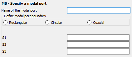
Figure 1. The MB - Specify a modal port dialog.
Parameters:
- Name of the modal port
- The label of the modal port.
- S1
- Point S1 situated on the FEM modal boundary.
- S2
- Point S2 situated on the FEM modal boundary.
- S3
- Point S3 situated on the FEM modal boundary.
Note that the modal port is only available in conjunction with FEM applied to dielectrics. A FEM modal port can only be applied on the boundary of a FEM dielectric region, situated on a planar surface.
The technology behind a modal port is a two dimensional FEM eigensolver that computes the eigenvalues (modal propagation constants) and eigenvectors (modal electric field distribution) for the associated infinitely long guided wave structure.
The memory requirement can, for a modal port, be estimated from the number of tetrahedral faces on the modal port and the order of the solution. The eigensolver by default uses second order basis functions. Changing the solver settings to use first order basis functions for the FEM (FP card) will also apply to the modal port analysis. The number of unknowns for a first order solution is roughly double the number of modal port triangles, and for a second order solution, 7 times the number of modal port triangles. The memory requirement scales with N2, where N is the number of unknowns.
The user should take note that memory and runtime scaling could become an issue with finely meshed modal port geometries. Note that when meshing modal ports, the default is to use second order basis functions on modal ports. Hence, a coarser mesh can be used than on the FEM/MoM boundary (where first order basis functions are always used).