SY Card
This card defines symmetry planes to reduce computation time and to reduce the number of elements to be meshed.
On the Solve/Run tab, in the Solution
settings group, click the ![]() Symmetry (SY) icon.
Symmetry (SY) icon.

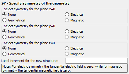
Figure 1. The SY - Specify symmetry of the geometry dialog.
Parameters:
- Select symmetry for the plane x = 0
- The type of symmetry, if any, in the YZ plane plane.
- Select symmetry for the plane y = 0
- The type of symmetry, if any, in the XZ plane plane.
- Select symmetry for the plane z = 0
- The type of symmetry, if any, in the XY plane plane.
- Label increment for the new structures
- After the labels are mirrored, the labels of the new elements are incremented with the value specified in this text box. Label 0 is, however, not incremented. The corresponding new elements will also have label 0. If this text box is empty or set to 0, the labels are not incremented. This means that the new elements will have the same label as that which they were created from.
All the conducting and/or dielectric triangles, segments, cuboids, tetrahedral volume elements, wedges, edges, Fock regions and polygonal plates that have been declared before the SY card, are mirrored. In addition, the second and third corners of the triangles are swapped, so that the direction of the normal vector is retained. Likewise the corners of image polygonal plates are rearranged to retain the normal direction. (The first corner point of the original polygon becomes the last corner of the mirror image.)
Sources are not mirrored. If, for example, a Hertzian dipole is placed on one side of the symmetry plane, the user must also place the correct image on the opposite side of the symmetry plane.
Multiple SY cards can be used and it is possible to mirror around more than one plane at the same time.