HE Card
The HE card creates a helical coil, consisting of wire segments.
On the Construct tab, in the Wires group,
click the ![]() Helix (HE) icon.
Helix (HE) icon.
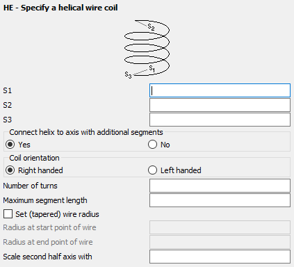
Figure 1. The HE - Specify a helical wire coil dialog.
Parameters:
- S1
- The start point of the coil's axis.
- S2
- The end point of the coil's axis.
- S3
- The start point of the windings.
- Connect helix to axis with additional segments
- Create connections from the two ends of the coil to the axis (at points S1 and S2). See also left side of Figure 2. If the connections are not generated, point S3 is a connection point. See also the right side of Figure 2.
- Coil orientation
- Indicate whether a right- or left handed coil should be created.
- Number of turns
- In this field the number of turns for the helix is entered. It need not be an integer number.
- Maximum segment length
- Maximum length of the segments, that are used for the windings in m (is scaled by the SF card). If this parameter is left empty, the value specified with the IP card is used.
- Set (tapered) wire radius
- If this item is checked, a tapered wire radius can be set. Normally the wire radius is set with the IP card. Checking this item overrides this radius for the current helix without affecting the default for later segments (The radius is in m and is affected by the SF card scaling factor.) The segments connecting to the axis are not tapered and have radii corresponding to the start point and end point respectively.
- Radius at start point of wire
- The radius of the wire at the start of the coil.
- Radius at end point of wire
- The radius of the wire at the end point of the coil.
- Scale second half axis with
- If this parameter is empty or is set to 1, a helix with a circular cross section is created. If set to , a helix with an elliptical cross section is created. Here gives the ratio of the two half axes, where a is the distance S1–S3. It is not recommended to generate elliptical helices with extremely small or extremely large axial ratios with a CAD system as the distortion formulation used in PREFEKO may fail in these cases.
Quite often modelling the geometry of the coil requires shorter segments than those used for straight wires. Thus the maximum segment length specified by the IP card can be overridden along the arc by setting Maximum segment length.
The windings are generated between the two points S1 and S2, that lie on the axis. The radius of the coil is defined by the distance between the points S1 and S3. For elliptical cross sections this is the length of one half axis and the other one is Scale second half axis times this length.
Example of HE card usage
The two coils in Figure 2 are created using the HE card.

Figure 2. Example of two coils created with the HE card. The coil on the right is coiled in the left handed direction.