Browsers supply a great deal of view-related functionality by listing the parts of a model in a tabular and/or tree-based
format, and providing controls inside the table that allow you to alter the display of model parts.
FE geometry is topology on top of mesh, meaning CAD and mesh exist as a single entity. The purpose of FE geometry
is to add vertices, edges, surfaces, and solids on FE models which have no CAD geometry.
Tools and workflows that are dedicated to rapidly creating new parts for specific use cases, or amending existing
parts. The current capabilities are focused on stiffening parts.
The AutoDamper entity is a force-velocity model designed to easily simulate a shock absorber used in ground vehicles.
The AutoDamper entity reads force-velocity data from a file written in the TeimOrbit format.
MotionView and MotionSolve support multiple tire models. The AutoTire auto entity can be added to a full vehicle model as a single entity or
as a pair.
MotionView and MotionSolve support multiple tire models. The AutoTire auto entity can be added to a full vehicle model as a single entity or
as a pair.
The SoftSoil Tire Graphics tab appears when a SoftSoil Tire
and corresponding SoftSoil Road property files are chosen. It provides the options to create
an animated SoftSoil graphics in HyperView. A check box is
provided to activate the graphics. A graphics system collector is available to choose the soil
graphics system, this soil system is created when generating the road using the road tools
(see Visualization - Road Tools). This will be used to create a
moving carpet type of graphics to show the SoftSoil deformation as the vehicle moves over it.
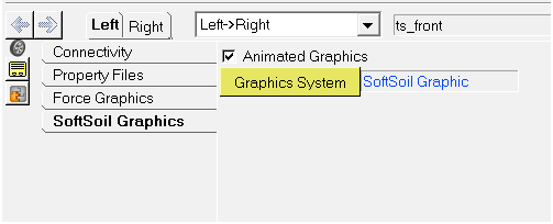
Figure 1. SoftSoil Tire Graphics Tab
When there are multiple AutoTires in a model, it is recommended to:
Use a single Graphic System in all of them.
Select/Clear the Animated Graphics option in all of them.
All the graphics that are created use the MotionSolve Grasub internally for animation in HyperView.