Single Lane Change
The Single Lane Change event drives the vehicle through a single lane change, attempting to follow the centerline of the defined lane. You can define the speed of the lane change, along with the lane dimensions. A steering controller is used to follow the path and a torque controller is used to maintain speed through the event. The event supports right and left lane changes. A plot template is available to plot the results.
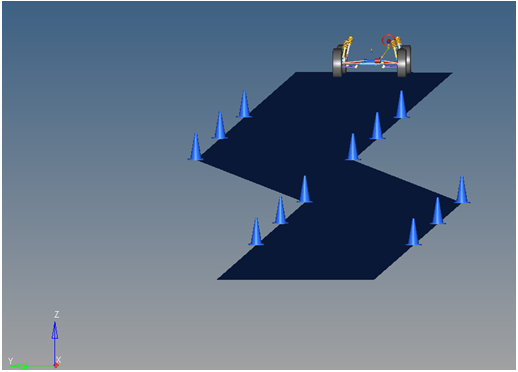
Figure 1. Single Lane Change Event

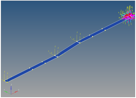
Figure 2. Top View of a Single Lane Change Path
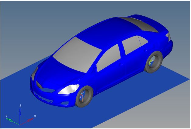
Figure 3. Vehicle Model with Body Graphics
The event is comprised of an initial straight section of road, a transition section, and a recovery straight section. In the initial straight section, the vehicle settles into a steady state condition. The transition section is the actual lane change. The vehicle recovers in the final straight section and terminates the simulation. The vehicle maintains a constant velocity (via the torque controller) in the event. The vehicle steering controller is designed to keep the CG of the body on a path at the centerline of the road.
The initial speed, longitudinal and lateral spacing of the cones, and lane graphics can be modified via the event form . The ground Z coordinate is a calculated value (the blue background designates a calculated value) and is calculated by subtracting the front left tire rolling radius from the front left tire CG Z location.
A test model runs this simulation in 60 seconds. Approximately 0.5G lateral is developed by the test vehicle model and default lane change parameters. Increasing the speed and lateral spacing of the cones increases the lateral G forces developed by the vehicle. As the vehicle approaches its limits of handling, the model will yaw excessively or will not complete the lane change. The error Could not Find Ideal SWA in 20 Iterations may be displayed in the log file, indicating that the steering controller is unable to follow the defined path.
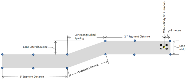
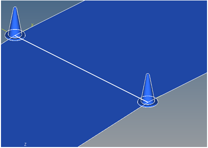
Figure 4. Single Lane Change Event - Road Graphics Parametric Definition
The cone spacing (laterally and longitudinally) and the lane width can be changed, along with the vehicle speed. Use the event form to change these parameters.
Attachments
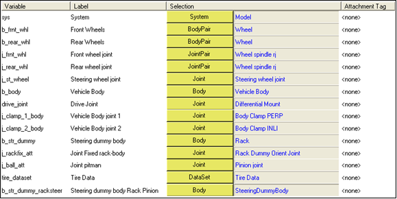
Figure 5. Single Lane Change Event - Attachments
| Variable | Label | Description |
|---|---|---|
| sys | System | The master system, in this case “Model”. |
| b_frnt_whl | mot_frnt_wheel | Front wheel body pair. |
| b_rear_whl | mot_rear_wheel | Rear wheel body pair. |
| J_frnt_whl | Front Wheel Joint | Revolute joint connecting the front wheels to the knuckle. |
| J_rear_whl | Rear Wheel Joint | Revolute joint connecting the rear wheels to the knuckle. |
| J_st_wheel | Steering Wheel Joint | Revolute joint connecting the steering wheel to the body or the steering gear input shaft to the body, if a steering column is not included. |
| B_body | Vehicle Body | The vehicle body. |
| Drive_joint | Drive Joint | The joint used to drive the vehicle, which varies depending on the drivetrain. It is typically the revolute joint in the drivetrain closest to the engine. |
| J_clamp_1_body | Vehicle Body Joint 1 | Vehicle body clamp one. One of two clamps used to hold the vehicle fixed during static simulation. |
| J_clamp_2_body | Vehicle Body Joint 2 | Vehicle body clamp two. The second clamp used to hold the vehicle fixed during static simulation. |
| b_str_dummy | Steering Dummy Body | The Rack in a rack and pinion steering system. The relay rod in a Parallelogram steering system. |
| J_rackfix_att | Joint Fixed Rack-Body | Rack dummy orient joint in a rack and pinion steering system. Idler Arm ball in a parallelogram system. |
| J_ball_att | Joint Pitman | The pinion joint in a rack and pinion steering system. The pitman arm ball joint in a Parallelogram system |
| Tire_dataset | Tire Data | Dataset containing the tire information from the tire system. |
| b_str_dummy_racksteer | Steering Dummy Body Rack Pinion | Steering dummy body in both parallelogram and rack and pinion steering systems. |
References
ISO 3888-2-2011 Passenger cars — Test track for a severe lane-change maneuver.
NATO Allied Vehicle Testing Publication AVTP: 03-160 Sep. 1991.
