HS-1025: Work with a HyperMesh and HyperMorph Model
Learn how to import size and shape variables to HyperStudy from
HyperMesh.
Before you begin, copy the model files used in
this tutorial from <hst.zip>/HS-1025/ to your working
directory.
The input variables are three shape variables:
xtrans
ytrans
radius
Each of these shapes are created by perturbing the mesh in the corresponding
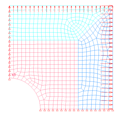
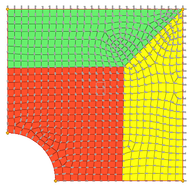
direction by 1 unit. Figure 1. Double Symmetric Plate Model Figure 2. Double Symmetric Plate Model with Shape Vectors
Perform the Study Setup
Start HyperStudy.
Start a new study in the following ways:
From the menu bar, click File > New.
On the ribbon, click .
In the Add Study dialog, enter a study name, select a
location for the study, and click OK.
Go to the Define Models step.
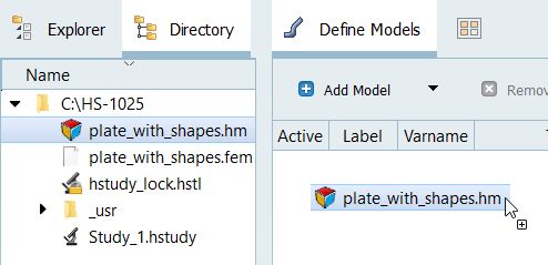
Add a HyperMesh model.
From the Directory, drag-and-drop the
plate_with_shapes.hm into the work area.
Figure 3.
In the Solver input file column, enter
plate.fem.
This is the name of the solver input file HyperStudy
writes during any evaluation.
In the Solver execution script column, select OptiStruct
(os).
Figure 4.
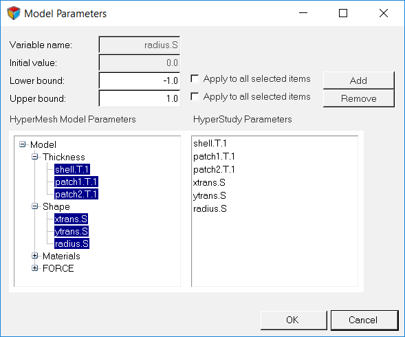
Click Import Variables.
In the Model Parameters dialog, select parameters to
import into HyperStudy.
Select the thickness and shape variables.
A total of 6 parameters should be selected.
Click Add.
Click OK.
Figure 5.
Go to the Define Input Variables step.
Review the input variable's lower and upper bound ranges.
Perform Nominal Run
Go to the Test Models step.
Click Run Definition.
An approaches/setup_1-def/ directory is created
inside the study Directory. The
approaches/setup_1-def/run__00001/m_1 directory
contains the input file, which is the result of the nominal run.
Create and Evaluate Output Responses
In this step you will create output responses, Mass and Displacement.
Go to the Define Output Responses step.
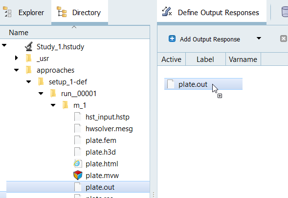
Create the Mass output response.
From the Directory, drag-and-drop the plate.out
file, located in
approaches/setup_1-def/run__00001/m_1, into the
work area.
Figure 6.
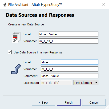
In the File Assistant dialog, set the Reading
technology to Altair® HyperWorks® and click
Next.
Select Single Item in a Time Series, then click
Next.
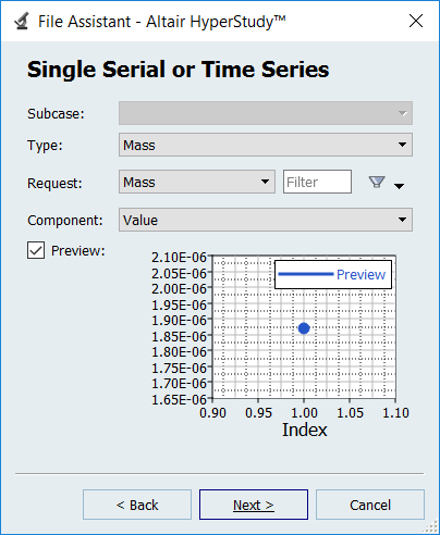
Define the following options, then click Next.
Set Type to Mass.
Set Request to Mass.
Set Component to Value.
Figure 7.
Label the output response Mass.
Set Expression to First Element.
Note: Because there is only a single value in this data source, [0] is
inserted after m_1_ds_1, thereby choosing the first (and only) entry
in the data source.
Click Finish.
Figure 8.
The Mass output response is displayed in the work area.
Create the Displacement output response.
From the Directory, drag-and-drop the
plate.h3d file, located in
approaches/setup_1-def/run__00001/m_1, into the work area.
In the File Assistant dialog, set the Reading
technology to Altair® HyperWorks® and click
Next.
Select Single Item in a Time Series, then click
Next.
Define the following options, and then click Next.
Set Subcase to Subcase 1 (Load).
Set Type to Displacement (Grids).
Set Request to N298.
Set Component to MAG.
Label the output response Displacement.
Set Expression to First Element.
Click Finish.
The Displacement output response is added to the work area.
 .
.