FE geometry is topology on top of mesh, meaning CAD and mesh exist as a single entity. The purpose of FE geometry
is to add vertices, edges, surfaces, and solids on FE models which have no CAD geometry.
An exploration is a multi-run simulation. Each exploration includes input design variables, and output responses.
Explorations may also include goals, consisting of an objective and constraints.
An input design variable is a system parameter that influences the system performance in the chosen output response.
Typical design variables may be a part's thickness, shape, or material property. Ranges, with lower and upper bounds,
are specified and the variable's value will vary within the exploration. The terms input, input design variable, and
design variable are used interchangeably.
Constraints need to be satisfied for an optimization to be acceptable. Constraints may also be associated with a DOE.
While not used in the evaluation of the DOE, constraints can be useful while visualizing DOE results. Limits on displacement
or stress are common examples.
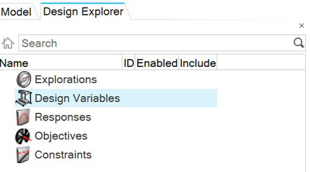
The Design Explorer Browser displays a hierarchical view of your
design setup and can be used to enable and disable exploration parameters.
From the Design Explorer ribbon, Exploration tool group, click the
Design Explorer tool.
The Design Explorer Browser opens in the browser
area.
Any defined parameters are displayed here. Multiple explorations may
be created in any given HyperWorks session.
Use the Enabled option to select the active exploration and include or
exclude desired design variables, responses, objectives, or constraints
before evaluating.
Note: Only one exploration can be enabled at a
time.