Coordinate Systems
There are various ways in which coordinate systems are defined, applied, and interpreted for an OptiStruct model.
- Basic Coordinate
System
The basic coordinate system is the built-in cartesian coordinate system in OptiStruct. In addition to being the default reference system for all other coordinate systems, it is also the default system in which the geometry of the structure is defined in.
- Local Coordinate System
A local coordinate system can be defined for any coordinate system input which allows referencing a system which is different from the basic coordinate system. It can also help in representing nodes on non-planar surfaces, like cylindrical or spherical surfaces. These can be represented in local cylindrical or spherical systems. OptiStruct supports three types of local coordinate systems, cartesian, cylindrical, and spherical. These can be defined using CORD1C, CORD1R, CORD1S, CORD2C, CORD2R, CORD2S, CORD3R, and CORD4R.
The local system is defined based on a reference coordinate system (for which the basic system is the default).
- Global Coordinate System
The global coordinate system is defined as a combination (or union) of all the coordinate systems (defined via the CD field on all GRID entries) in OptiStruct. If the CD field on all GRID entries are left blank, the global coordinate system is the same as the basic coordinate system. The global stiffness matrix is assembled in the global coordinate system without transformation to the basic system.
- Element Coordinate System
Element coordinate systems for each element type typically identify certain element attributes, such as orientation of section properties, offset vectors for beams, shell offsets, and so on. The element coordinate system is also used for output certain results such as element forces, moments, and stresses. For most elements, the element coordinate system is automatically calculated based on the element connectivity and geometry. Output such as stresses and strains in particular formats (H3D and OP2) are output by default in the elemental system.
- Material Coordinate System
Material coordinate system can typically be defined explicitly via corresponding fields on various element and/or property entries. These can be used to define the orientation of material properties (including orthotropic, anisotropic, and composite materials). Certain outputs such as stresses and strains in particular formats (HM, PUNCH, OPTI) are output in the material system by default.
- Define Model GeometryThe geometry of the model is defined through grids represented in the Reference Coordinate System. This coordinate system is defined in the CP field on the GRID Bulk Data. The default is the basic coordinate system.
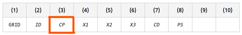
Figure 1. - Displacement OutputThe degrees-of-freedom, displacement output, and constraints of the grids are applied and interpreted in the Displacement Coordinate System. This coordinate system is defined in the CD field on the GRID Bulk Data. The default is the basic coordinate system.
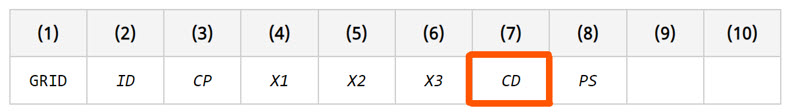
Figure 2.
Output
- Displacements are output in the displacement coordinate system identified as the collection of all CD systems defined on the GRID Bulk Data.
- Stresses and strains are always output in the elemental system in the H3D and OP2 formats and are output in the material system in the HM, PUNCH, and OPTI formats.