Area Panel (Connectors)
Use the connector Area panel to create connectors that represent connections of larger regions, such as adhesives. These connectors can later be realized as standard or custom weld representations.
Location: Connectors module
The test points of an area connector are characterized by nodes of an internal mesh dedicated to the connector. During connector creation the internal mesh can be created by adopting the mesh used for location, or the defined region is automeshed with a certain mesh type.
When the Area panel is active, only area-type connectors display in the modeling window; graphics for other connector types are suppressed until you exit the panel.
Subpanel Organization
- Area Subpanel
- Create and realize area connectors.
- Create Subpanel
- Create, but do not realize area connectors.
- Realize Subpanel
- Realize existing area connectors (no creation or editing possible).
- Edit Subpanel
- Edit existing area connectors.
- The first column contains everything related to connector creation and link detection.
- The second column contains everything related to realization type, post script and property assignment.
- The third column contains everything related to the final connection to the link entities.
Connector Creation and Link Detection Options
| Option | Action |
|---|---|
| location | Specify the location of the connector to be created.
|
| width | Width of the connector area centered along the
line. Note: Only available when the location is set to lines
or nodelist.
|
| offset | Connector is offset from the free mesh edge along the link by
this distance. Note: Only available when the location is set to
lines or nodelist.
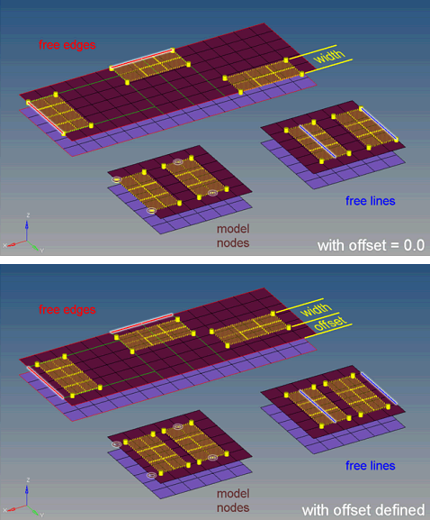 Figure 2. |
| connectors | Select the connector(s) to be realized. |
| line combine |
Create one seam connector for each sequence of lines and each single line. With this option enabled, a sequence of lines will be internally treated as on line. This option is preferred for continuous seams together with realization types where the body element is positioned between the weld points of all quad and hexa seam realizations. With this option, neither the vertices nor the start point
and end point of the initial lines are considered, and there likely will not be any
weld points at the exact positions.
Note: Default setting when location is set to
linelist.
|
| mesh type | Select the mesh type to mesh the connector with. Note: There is no interactive mesh manipulation
available. A few more options can be used during editing an
area connector.
|
| mesh size | Specify the mesh size the connector should be meshed with. |
| connect what |
Select the entities to
become link candidates. Link candidates are certain entities of a chosen link
type, which are supposed to be connected during the realization. Entities
outside the tolerance are not taken into account.
Note: Connectors can be created with different
types of entities; for example, a connector can be defined by selecting a
component on one side and an assembly on the other side. This can be done by
creating a connector to specify one of the entity types and selecting that
entity. Add the second entity by updating the connector via the add links
functionality in the Connector browser or the Add Links panel.
|
| num layers |
Define how many thicknesses (layers) have to be connected at the connector position. This number is predefined as 2. There is not a field in the this panel where you can set the number of layers; however, you can find the number of layers in the Connector browser. When link detection is performed the valid connector links are established with respect to the given tolerance and the selected link candidates. By default the links are reduced to the minimum needed. The number of links is typically higher than the number of layers, because a valid pair of projections need to be found per test point. |
| tolerance |
Define a distance from the connector location (per each test point). Only entities within this tolerance can be taken into account for the link detection and the final realization. Thus, the tolerance is used twice: first for the link determination and again for the realization. In the second step the tolerance is used to verify whether adequate link candidates are available to be connected. During pure connector creation on the Create subpanel, the tolerance is used for the link determination, but not necessarily stored on the connector unless the checkbox in front of the tolerance field is marked. In this way different tolerances can be used. The tolerance used during the realization process is always written to the connector. |
| connect when |
Select when to perform link detection.
|
| reconnect rule |
While realizing the connector, HyperLife Weld Certification
looks for link entities based on the re-connect rule.
Tip: This option is
useful in situations where the parts to be connected have been
changed/replaced.
|
Post Script and Property Assignment Options
| Option | Action |
|---|---|
| type |
Select the realization type which should be used. The
realization type is a description of the FE representation.
Note: The available
realization types are dependant on the configuration file loaded under fe file
on the general connector Options panel.
|
| fe file | A default feconfig.cfg file that is
available in the installation is automatically loaded. If you
choose to add a unique realization type, copy this file into the
user home directory and add custom types. Click ... to load a user-modified feconfig.cfg file, if necessary. |
| post script treatment |
Choose whether or not a post script has to be used for
the specific realization type. These scripts are used to automatically create
materials, properties, and/or contacts necessary for realizing the connectors.
|
| elems to current comp / connector comp |
Select which component the FE representations
are stored in once they have been realized.
Note: Only available in the realize subpanel when post script treatment is set
to no/skip post script.
|
| property treatment |
Select a property treatment.
Note: Only available when post script treatment is set to no/skip post
script.
|
| direct property assignment |
Directly assign the property, otherwise assign the
property to the destination components.
Note: Only available when property treatment
is set to property =, and the solver interface is Nastran, OptiStruct, Radioss or Abaqus.
|
Hexa Realization Options
| Option | Action |
|---|---|
| coats | Defines the number of hexa elements required along the
thickness. Note: Multiple
solid coats are supported when adhesive-hemming is
selected.
|
| thickness |
Select a method for defining the thickness of a hexa
weld.
Note: The exact hexa position is also influenced by
the option consider shell thickness and offset for hexa
positioning.
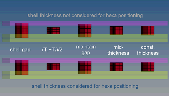 Figure 3. |
| direction node | Define the direction node. |
Penta Realization Options
The Penta (Mig) realization type is the primary form of penta realization for areas.
Edit Subpanel Options
| Option | Action |
|---|---|
| multiple nodes: connector | Select the area connector that you would like to trim. Once you alter the selected connectors' options, click edit to update the selected connectors with respect to the new settings. The connectors will become unrealized. |
| multiple nodes: node list | Select a nodelist on the area connector or a nodelist on
existing nodes.
|
| snap to connector point | Trim the connector at the closest connector point per each
selected node within the specified tolerance. By default this option is selected, and the tolerance is set to 1.0. If you selected a nodelist on existing nodes, this option will have no influence on the trimming behavior. |
| delete smaller connector piece | Delete the smallest connector piece when the connector is trimmed. |
| trim | Trim the connector into a new, unrealized connector. The new connector contain all of the information that was retained from the original connector. |
| Option | Action |
|---|---|
| location | Select connectors to edit. Once you alter the selected connectors' options, click edit to update the selected connectors with respect to the new settings. The connectors will become unrealized. |
| mapped type | Select the shape of elements to use on surfaces that can be mapped to simple geometric shapes like a triangle, rectangle, or rhombus. |
| free type | Select the shape of elements to use on more complex surfaces that cannot easily map to simple shapes. |
| size control | Keep elements roughly the same size. |
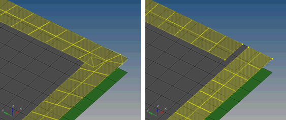
| skew control | Prevent the mesh from producing highly-skewed elements. |
| link opposite edges | Force opposite edges of the area connector to use consistent
edge densities, provided that the starting densities are close
enough. This creates tapered lines of elements, instead of using
trias to transition between inconsistent densities. Figure 4. Link Opposite Edges Example. Meshing with (left) and without (right) linked edges. |
| size and bias/edge deviation | Select meshing criteria.
|
Command Buttons
| Button | Action |
|---|---|
| mesh | Apply the mesh using the new settings when remeshing connectors. |
| options | Open the Connector Options panel, where various settings can be defined. |
| create | Create the connector(s) with provided input (if sufficient). |
| reject | Undo the last action. |
| return | Exit the panel. |