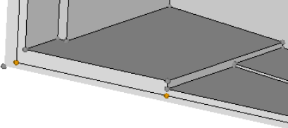
Auto Midsurface Tool
Use the Auto Midsurface tool to extend and modify midsurfaces.
Auto Extraction Subpanel
| Option | Action |
|---|---|
| entity selector | Select the surfaces or solids from which you wish to extract midsurfaces. |
| closed solid / incomplete solid |
|
| select connected surfaces | Automatically select
all of the attached surfaces once you select a single
surface. Note: Only available when incomplete solid is
selected.
|
| outbound normals (red) | Indicate that the
normals of the selected volume point outside the enclosed
volume. Clear this checkbox when the normals point inside the
enclosed volume. The normals of the selected surfaces are
displayed as soon as your selection is completed.
Note: Only
available when incomplete solid is
selected.
|
| color display normals / vector display normals | Choose how the normal
direction of the selected surfaces is displayed. Color display
is recommended. When normals are consistent, color display normals colors the outer surfaces of the model red or blue, but never a mixture of both. For most models, normals are automatically oriented consistently. |
| fix normals / reverse normals | Reorient surfaces that
do not have a consistent normal direction.
|
| extract | Extract the midsurface. |
Extraction Options Subpanel
| Option | Action |
|---|---|
| offset + planes + sweeps / offset + planes / offset / skin offset |
|
| align steps/keep step jumps | In the case of a part
that has different "steps" of thickness, such as a flat sheet
that is twice as thick at one end as the other, but uses an
abrupt step-like change in thickness instead of a constant slope
or curve choose how to manage steps.
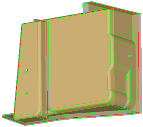
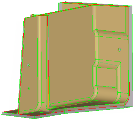
 Figure 5. Valid Steps. Steps are in Front of a Single Surface  Figure 6. Invalid Steps. Steps are in front of multiple surfaces. Note: Only available
when you select offset.
|
| auto mid position / user mid position |
Note: Only available when you select offset and align
steps.
|
| allow rerun | Go to the Edit
Collapsed Lines subpanel, from which you can enable
visualization settings to display point associations on the
midsurface after extraction, and create and edit collapsed
lines. When extracting a new midsurface, the midsurface is generated using the collapsed lines that were automatically found during the initial midsurface extraction and the lines that you manually collapsed. If allow rerun is disabled or the allow rerun switch is set to no rerun or prepare for rerun, then the lines that you manually collapsed will not be used when a new midsurface is extracted. |
| use base surfaces | Go to the Edit Base
Surfaces subpanel, from which you can specify a distance from
the base surfaces of multiple solids, that you wish to treat as
if they were continuous, in order to generate
separate-but-aligned midsurfaces during extraction. If use base surfaces is disabled, new midsurfaces will not be generated at the specified distance from the selected base surfaces. The setup of the base surfaces that you modified will be retained for future use as long as you do not delete them. |
| thickness bounds/no thickness bounds | Choose whether or not
to specify thickness bounds for the plates in the part.
|
| max R/T ratio | This ratio is taken
into account on T-, X- and more complex connections only. On a
curve without a T-connection (like on the right side on the
picture) it does not apply.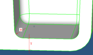 Figure 8. Since in many cases the fillet is not an exact cylinder and has a variable curvature, or the fillet cross-section is not orthogonal to the fillet axes, in reality the length on the curve at the fillet is taken and R is recalculated from this length as if it were an arc of a circle. |
| thickness based stitch tol | Perform the final
stitching of midsurfaces with a locally-defined tolerance of 1/5
of the local thickness. Clear this checkbox to use the global cleanup tol specified in the Options panel for stitching. This method is recommended when an extensive manual edit of the auto midsurfacing result is expected, because stitching comparatively distant midsurfaces may misrepresent the geometry of the model and affect following operations on geometry. |
| extract by component/cross components | This option is useful
when you are trying to extract the midsurface of multiple parts
in a single step.
|
| result in Middle Surface comp/result in current comp / sorted results | Choose where to
organize midsurfaces upon creation.
|
| sort Middle Surface comp into | Choose how to sort the
middle surfaces immediately following extraction.
Tip: Manually sort the Middle Surface component
after extraction from the Sort subpanel.
|
Message Options Subpanel
- Plate type change
- Deleting plate information
- Pre-existing plates/base surfaces
- Plates/base information conflicts
