Detach Solids
Use the Boolean: Detach tool to separate selected solids from neighboring solids that share one or more common faces.
Shared or partition faces between selected solids and surrounding solids duplicate to become bounding faces of the separated solids. Partitioning faces within the selection are maintained after they are detached from the rest of the model.
-
From the Geometry ribbon, click the tool.

Figure 1. -
In the microdialog, select one of the following
options:
Option Description 
Detach all
Selected solids detach from neighboring solids and each other.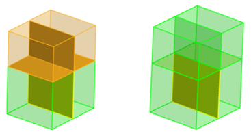 Figure 2.
Detach from each other
Selected solids detach from each other but maintain an interface with neighboring solids.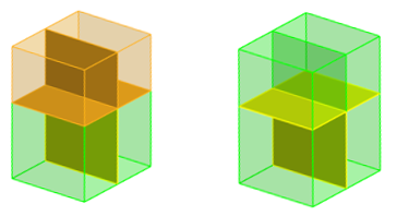 Figure 3.
Detach from not selected
Selected solids detach from neighboring solids while maintaining an interface within themselves.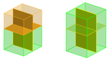 Figure 4.