Preferences Dialog
From the Preferences dialog, you can access various MotionView options for your model.
Starting in version 2021.2, all client preferences are available in a single dialog which can be invoked from File > Preferences.
Appearance
Set various display options for MotionView.
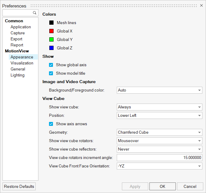
Figure 1. Preferences - MotionView - Appearance
| Colors | To change the color of one of the following features, click on a color box, select a new color from the palette, and click OK. | |
| Mesh lines | Changes the mesh line color of the graphics. | |
| Global X/Y/Z Axis | Changes the colors of the global X, Y, and Z axes. | |
| Parametric field background | Changes the background color of all parametric fields. | |
| Show | Global axes | The global axes can be displayed in the lower left corner of the MotionView window. Click the Global axes check box to toggle the display of the axes on or off. |
| Model Title | The model title can be displayed at the top of the window. Click the Model Title check box to toggle the display of the title on or off. | |
| Image and Video Capture | Select a color setting for the background/foreground
during image and video capture.
|
|
| View Cube | Select from the various View Cube display options: | |
| Show view cube | Use this option to set the visibility of the view cube. The view cube can be set to be visible Always|Never|Mouseover. When set to Mouseover, the view cube is visible when the mouse is over its position. | |
| Position | Set the location of the view cube. The view cube can be positioned in the Lower Left | Lower Right | Upper Left | Upper Right corner of the modeling window. | |
| Show axis arrows | Set the arrow pointer visibility of the Global Axis triad. | |
| Geometry | Sets the shape of the view cube. Chamfered Cube | Simple Cube. The Chamfered Cube offers additional view orientation choices than the Simple Cube. | |
| Show view cube rotators | Use this option to set the visibility of the view cube rotators. The view cube rotators can be set to be visible Always|Never|Mouseover. The rotators can be used to rotate the views both in plane or about the plane of modeling window. | |
| Show view cube reflectors | The reflectors can be used to set the view to the planes that are hidden. The reflectors can be set to be visible Always | Never | Mouseover. | |
| View cube rotators increment angle | Angle in degrees that the view would rotate when using the rotators. | |
| View Cube Front Face Orientation | Defines the Front face direction of the View cube. The available choices indicate the plane of the global the front face of the cube would be parallel to. For example, -YZ would make the Front face parallel to the YZ plane with the side along the direction perpendicular to the plane indicated by the negative sign (clockwise rotation of Y towards Z) imagining the triad at the center of the cube. |
|
Visualization
Set the zoom factor and rotation angle options for MotionView.
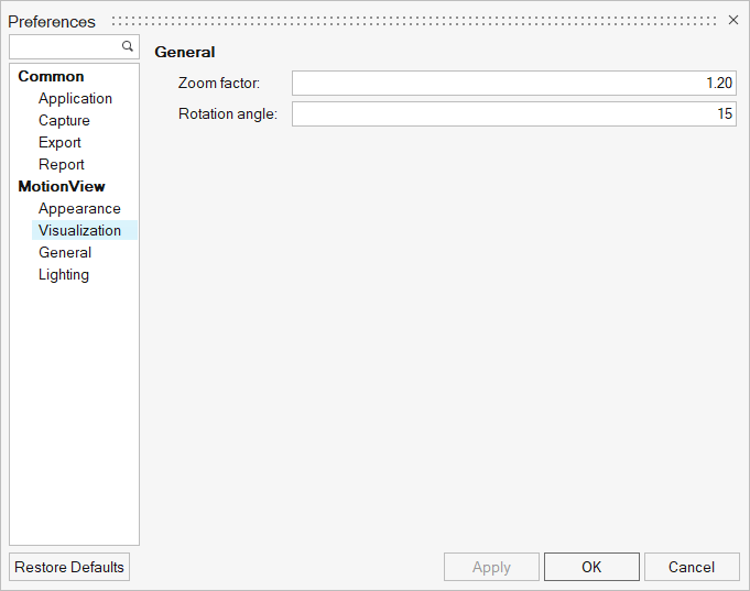
Figure 2. Preferences - MotionView - Visualization
| Zoom factor | Specifies the multiplication factor that is used to increase or decrease the scale of the current view while zooming using the scroll wheel. The default is 1.20. |
| Rotation Angle | Specifies the increment (in degrees) that will be used when rotating a model using the view controls toolbar. The default is 15. |
General
Select Check Model and Build Model options for MotionView.
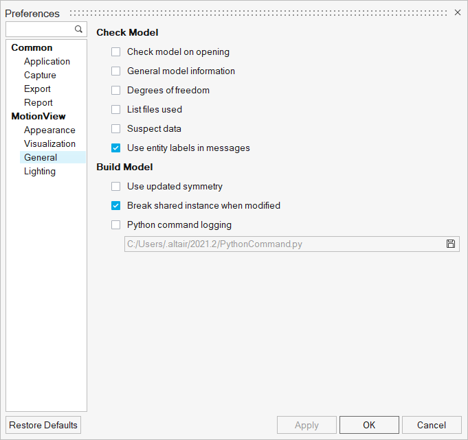
Figure 3. Preferences - MotionView - General
Check Model
The Check Model options allow you to select which information from the model file will be
displayed when the Check Model tool ![]() is run.
is run.
| Option | Description |
|---|---|
| Check model on opening | Checks the model immediately upon opening a model. When this check is off, the model is not checked for errors upon opening. |
| General model information | This option provides general information about the model. The information
contains the count of each type of entity apart from the number of inactive system
or analyses.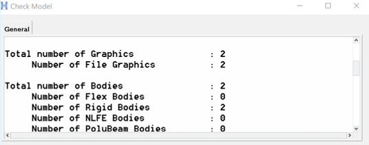 Figure 4. |
| Degrees of freedom | Provides degrees of freedom information. The total DOF is calculated by
including all DOFs contributed by bodies and subtracting DOFs removed by
constraints: Model DOFs = DOFbodies - DOFconstraints Refer to the DOF Tables section
below for details on body and constraint DOF contribution.
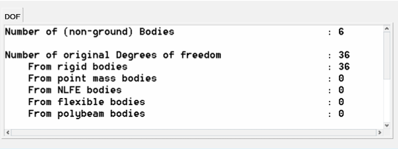 Figure 5. Note: The DOF calculation does not consider
redundant constraints.
|
| List files used | This option lists the reference files that the model uses for flex bodies, graphics, and curves. |
| Suspect data | This option captures possible suspect data that could cause problems during
solution. The suspect data could include:
|
| Use entity labels in messages | With this option turned on, the messages posted in the message log will refer to MotionView entities by their label. Otherwise, the message will refer to the entities by the variable names. |
- Degree of Freedom Tables
-
Body Type Adds DOF Rigid body 6 Point mass body 3 Flex body - CMS Number of active modes in the flex body NLFE body 12 x number of points defining the NLFE body Polybeam body 6 x number of points defining the Polybeam Joints Type Removes Translation DOF Removes Rotation DOF Total DOF Removed Atpoint 3 0 3 Inline 2 0 2 Inplane 1 0 1 Orientation 0 3 3 Parallel Axis 0 2 2 Perpendicular 0 1 1 Ball 3 0 3 Constant Velocity 3 1 4 Cylindrical 2 2 4 Fixed 3 3 6 Planar 1 2 3 Point to Curve 2 0 2 Revolute 3 2 5 Translational 2 3 5 Universal 3 1 4 Advanced Joints Type Removes Translation DOF Removes Rotation DOF Total DOF Removed Point to Curve 2 0 2 Curve to Curve 1 2 3 Point to Surface 2 3 5 Curve to Surface 2 3 5 Surface to Surface 2 3 5 Point to Deformable Curve 1 3 4
Build Model
| Option | Description |
|---|---|
| Use updated symmetry | Use true symmetric inertia properties for body pairs. When off, the product of inertia values of the follower side has the same values as on the leading side. |
| Break shared instance when modified | Use this option to control how shared instances should be handled while
modifying them:
See the Managing Shared Definitions topic for additional information. |
| Python command logging | Activate this check box to enable saving commands in the Python window to a log file. See MotionView Python Reference Guide. |
Lighting
Determine the light sources to be used for illuminating graphics in MotionView.
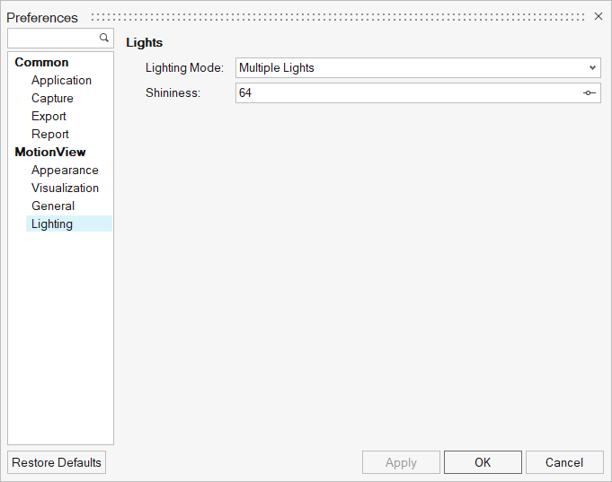
Figure 6. Preferences - MotionView - Lighting
- Multiple Lights
- Use the standard placement of multiple lights. The following option is
available:
Shininess Use the slider bar to set the shininess (0-128). - Single Light
- Specify the shininess, direction, and specularity of the light. Any combination of
light properties may be used to light the graphic.
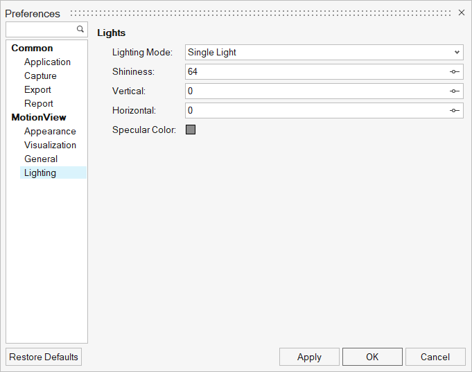
Figure 7.Shininess Use the slider bar to set the shininess (0-128). Vertical Use the slider bar to set the vertical direction of the light. Horizontal Use the slider bar to set the horizontal direction of the light. Specular Color The specular color defines the color reflected back on shiny surfaces. To change the color of the graphic, click on the color box, select a new color from the palette, and click OK Tip: To disable specular highlighting, set the specular color to black.