Model Browser
The Model Browser allows you to view the MotionView model structure while providing display and editing control of entities.
The Model Browser resides on a tab in a Tab Area sidebar.
There are
two types of folders in the Model Browser: Container
folders, ![]() ,
and Entity folders,
,
and Entity folders, ![]() . Container
folders can represent either a System, Assembly, or an Analysis. These folders can
contain entity folders and other container folders as applicable. Each entity folder
contains entities of a particular type; such as springs, joints, etc.
. Container
folders can represent either a System, Assembly, or an Analysis. These folders can
contain entity folders and other container folders as applicable. Each entity folder
contains entities of a particular type; such as springs, joints, etc.
The Model Browser can be turned on or off using the Model Browser option located within the View pull-down menu. A check mark indicates the Model Browser is activated for display in the Tab Area.
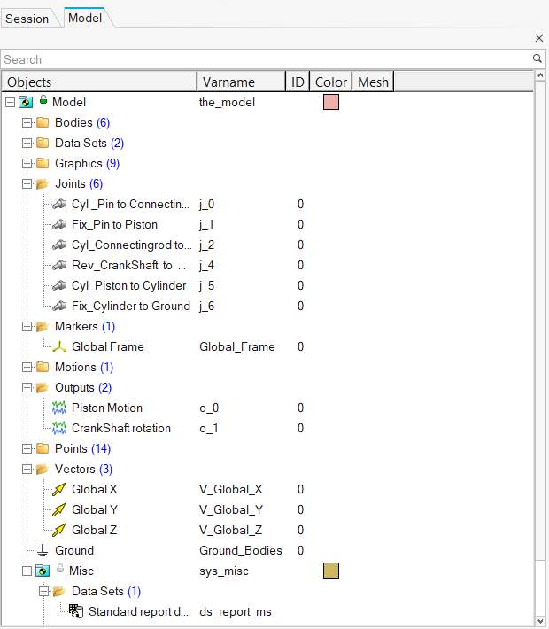
Figure 1. Model Browser displaying many of various the entities available in MotionView
- Global default entities (such as Ground Body and Global Vectors) are listed at the beginning, under the Model folder, followed by the other container folders.
- All of the entity folders within the container folders in the MotionView session will be listed in the tree in alphabetical order (for example: Bodies, DataSets, Markers, etc.).
- Multiple entities of the same type are collected into a folder in the tree structure.
- Each folder can be expanded or collapsed to display or hide its contents.
- The variable name of each entity is displayed in the tree.
- The ID, color, and display style of entities also display in the Project Browser, when appropriate.
- The Browser Context-Sensitive Menu (available by right-clicking within the Project Browser) offers a variety of operation choices which are relevant to the entity and context.
- Entities can be searched using keyboard inputs, as well as the Find tool.
Entity Selection
The Model Browser provides a powerful and easy way to find and query systems/entities, as well as to select entities for editing. When a system or entity is selected from the Model Browser, the system or entity is highlighted in the graphics area (if the entity has a graphic representation) and the corresponding entity panel is displayed in the bottom of the window.- Left-click to select & highlight an entity in the browser – the entity is also highlighted in graphics area. Information related to the entity is displayed in the panel and available for modification.
- <Ctrl> + left-click to select multiple entities in both the browser and graphics area.
- <Shift> + left-click to select multiple (two or more) entities within the range in the browser and the graphics area.
- Right-clicking highlights components in the list and invokes the Browser Context-Sensitive Menu – no highlighting of the entity in graphics area will occur with this operation.
- Left-click to select entities.
Selected entities' line items highlight within the browser.
Column Headers/Display Controls
- Objects
- Displays the labels of the items/entities that comprise the model.
- Varname
- Displays the variable name of each entity. The varname of entity is commonly used when constructing parametric expressions or when debugging models, however they cannot be changed or modified.
- ID
- The ID column displays the ID of each entity (if available). Pair IDs are shown comma-separated (0,0). Entity IDs will only display in the Model Browser after a Check Model has been run, and they cannot be modified from the browser.
- Definition
- Displays the definition name for definition based entities such as: System, Assembly, Analysis, DataSets, Templates, Forms, and CommandSets.
- Color
- Containers and entities can be colored individually, the Model Browser allows you to set each entity’s color without using the Graphic Entity Attributes panel. When appropriate, the currently assigned color for an entity displays in the Color column. To change an entity’s color, right-click on the current color in the Model Browser, click on Change Color, select a new color from the Colors/Materials dialog, and then click OK. When the color of a system is changed, the new color 'cascades down' having an effect on the colors of its children; the colors are updated in both the browser (icons) and in the graphics window. Similarly, changing the color of the 'Model' (top level container) will affect the color of all of the entities in the Model, therefore this feature should be used with caution.
- Mesh
- Entities have several display states, based on a combination of their
elements and their geometry. You can select these display modes by
clicking the small icons in the Mesh column for each entity. Left or
right-clicking allows you to open the Mesh/Shade dialog, from which you
can choose the new style:
- Mesh
- There are four line options to apply to model components:
Mesh Lines

Feature Lines

Edge Lines

No Lines

Click the appropriate button to display the desired feature; click another button to remove the feature.
- Shaded
- Entities can be displayed with no shading, opaque, using
material, or transparent.
Click
 to display the selected
entities with no shading.
to display the selected
entities with no shading.Click
to display the selected
entities as opaque. Opaque entities are solid and hide
the entities behind Click
 to display the selected
entities with the selected material.
to display the selected
entities with the selected material.Click
 to display the selected
entities as transparent. Transparent entities are
see-through and reveal the obscured entities behind
them.
to display the selected
entities as transparent. Transparent entities are
see-through and reveal the obscured entities behind
them.
Keyboard Shortcuts
- Up arrow key
- Moves up the browser tree.
- Down arrow key
- Moves down the browser tree.
- Left arrow key
- Moves quickly up the browser and collapses various folders along the
way. For example, when an entity is selected and the left arrow key is
pressed four times:
- takes you to the entity folder
- collapses the entity folder
- takes you to the next parent folder
- collapses the next parent folder
- Right arrow key
- Expands a collapsed folder. Subsequent use will take you to the first available object within the folder (until an entity is encountered).
- CTRL+Up arrow key
- Scrolls up the browser tree without selecting the entity.
- CTRL+Down arrow key
- Scrolls down the browser tree without selecting the entity.
- Spacebar
- Selects the item that is currently chosen with the 'CTRL+Arrows'.
- Backspace
- Takes you from the active item in the browser tree to the parent item (without collapsing the folders).
- CTRL+HOME
- Takes you to the top level container 'Model' (at the top of the browser).
- CTRL+END
- Takes you to the last entity (at the bottom of the browser).
- CTRL+X
- Cuts the selected entity.
- CTRL+V
- Pastes a previously cut entity into the selected container.
- CTRL+A
- Selects all of the entities listed in the browser.
- CTRL+\
- Unselects all of the entities listed in the browser.
- DELETE
- Deletes the currently selected entity (after confirming the action in the Confirm Delete dialog).
- SHIFT+DELETE
- Allows you to delete the currently selected entity immediately, without being prompted by the Confirm Delete dialog.
- F2
- Allows you to rename the selected entity.
- CTRL+F
- Displays the Find dialog, which can be used to find an entity.
- SHIFT+F10
- Displays the context menu that appears on the right-click.
Entity Icons
- Reference Entities
-
Entity Icon Points 
Bodies 
Vectors 
Markers 
Curves 
Spline3D 
Graphics 
Surfaces 
Deformable Curves 
Deformable Surfaces 
- Constraint Entities
-
Entity Icon Joints 
Motions 
Couplers 
Gears 
Advanced Joints 
General Constraint 
- Force Entities
-
Entity Icon Forces 
Bushings 
Fields 
Spring Dampers 
Beams 
Polybeams 
Contacts 
- Control Entities
-
Entity Icon Solver Variables 
Solver Arrays 
Solver Strings 
Solver Differential Equations 
Control SISOs 
Sensors 
- General MDL Entities
-
Entity Icon Outputs 
- Definition Based Entities
-
Entity Regular Icon Shared Icon Analysis (Inline) 

CommandSets 

DataSets 

Forms 

GraphicSystems 

Systems 

Templates 

Refer to the Managing Shared Definitions topic for additional details.