Contour Beam Stress
Use the Beam Stress tool to display a contour of stress distribution on a tessellation of a beam cross section.
Stress distribution is recalculated from vectors “1D Forces” and “1D Moments” datatypes at first section (node 1) of a beam. It does not use any stress recovery points from solver output.
You can control which of the force’s contributions to consider during the stress calculation.
Stress is calculated using Elasticity theory (reference: Analysis and Design of Elastic Beams: Computational Methods, Walter D. Pilkey).
Restriction:
- Property must refer to either a Standard or Solid beam section.
- A tessellation of the section is generated on-demand to display the stress contour.
- The result file needs to include vector datatypes “1D Forces” and “1D
Moments”.
- OptiStruct native *.h3d lacks such vectors and won’t work.
- *.op2, *.xdb file, or any translation in *.h3d file will work.
- Currently, only the resultant force/moment at the first node of a beam is considered during the stress calculation.
-
From the Post ribbon, click the Beam Stress tool.

Figure 1. -
Use the drop-down on the guide bar to select the stress
quantity to evaluate.
Shear Y and Z are with respect to the elemental system.
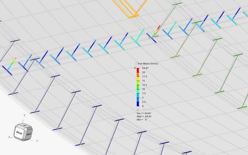
Figure 2. Von mises stress on selection -
Select force and moment in the microdialog.
The selected stress quantity is calculated from the forces and moments contributions acting on first node of the beam element.
-
By default, the stress datatype is evaluated from the full acting load:
(Fx,Fy,Fz) & (Mx,My,Mz). You can disable any of these components to
evaluate the resultant stress without such contributions.
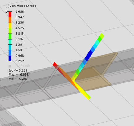
Figure 3. Von Mises stress due to resultant force/moment
Figure 4. Von Mises stress without axial force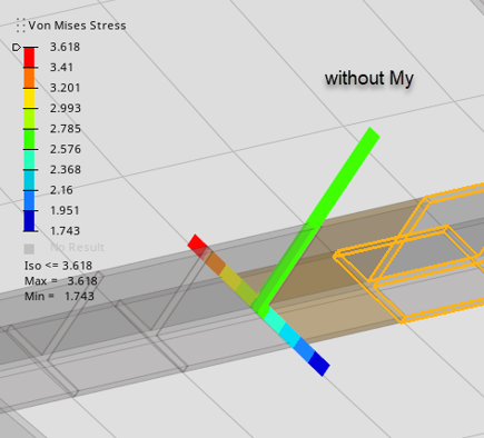
Figure 5. Von Mises stress without bending moment My
-
By default, the stress datatype is evaluated from the full acting load:
(Fx,Fy,Fz) & (Mx,My,Mz). You can disable any of these components to
evaluate the resultant stress without such contributions.
-
Selected beams can be contoured all at once by clicking
 on
the guide bar. Otherwise, clicking
Find enters a model tour with prev/ next options to
navigate across the selection.
During the model tour, the option Normal view automatically sets the view normal to the section and fits the view on the element.
on
the guide bar. Otherwise, clicking
Find enters a model tour with prev/ next options to
navigate across the selection.
During the model tour, the option Normal view automatically sets the view normal to the section and fits the view on the element. -
Set display options by clicking
 on the guide bar.
- Mesh mode
- The default stress calculation is performed using a meshed section.
-
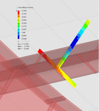
Figure 6. Coarse mesh, Contour elements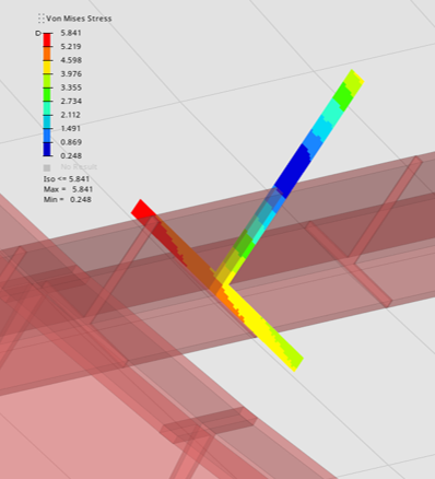
Figure 7. Fine mesh, Contour elements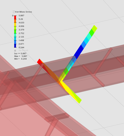
Figure 8. Fine mesh. Contour nodes - Scale Factor
- If beam sections are small compared to the model size, it is possible to scale them.
-
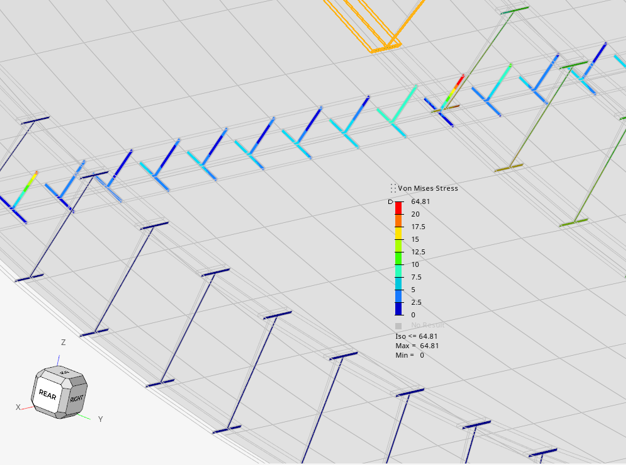
Figure 9. Sections in default size (scale 1)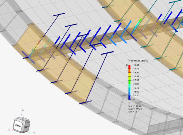
Figure 10. Sections in scale 2 - Contour Type
- Display contour on Element (default) or on Node (see Figure 8).
Changing any of these options or force contributions/subcases will auto-update the active contour.