Graphical Selection
Select and deselect entities to modify with other HyperWorks tools. Selected entities are outlined to indicate their selection state.
Hover over an entity to highlight it.
In idle mode, entities can be selected from either the modeling window or the browser area. Selecting an entity in the modeling window automatically selects the corresponding entity in the browser and vice versa.
When working in a tool, entities should be selected from the modeling window.
Entity Selectors
Use entity selectors to specify which type of entity you are able to select.
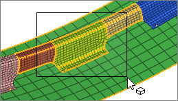
Entity selectors act as a filter by limiting your selection to a single entity type in the modeling window. For example, if an entity selector is set to Surfaces, only surface are available for selection. If it is set to Points, you can draw a window around the entire model and only the points will be selected. After performing a selection, the number of selected entities appears in parenthesis.

Figure 1.
If a selector supports multiple entity types, click the arrow to view a drop-down menu of available options.
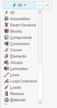
Figure 2.
Entity selectors do not affect your selection in a browser. The entity selector in the modeling window will automatically update to match the selected entity type. You're also able to select multiple entities of different types in a browser.
- Use keyboard shortcuts to change the active entity type in an entity selector.
- In idle mode, convert your selection to a new entity type by changing the entity selector. For example, if you select elements, and then set the entity selector to nodes, all of the nodes associated with the selected elements will be selected.
Select Single Entities
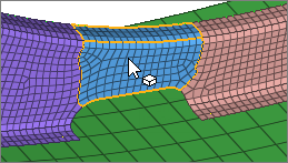
Figure 3.
Append and Remove Entities From a Selection
-
In the modeling window:
- Append entities to your selection by holding Ctrl while left-clicking.
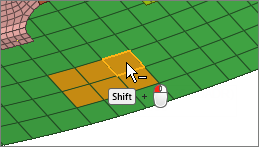
- Remove entities from your selection by holding Shift while left-clicking.
Figure 4.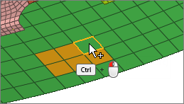
-
Clear your selection in the following ways:
- Left-click in empty space.Note: Only available in idle mode.
- Click
 on an active entity selector.
 - Press Backspace to clear
the active entity selector or press
Esc to clear all
entity selectors.
(HyperMesh only)
- Left-click in empty space.
Select Multiple Entities Simultaneously
- For box, circle, or freehand selection, click-and-drag to draw a selection window.
- For polyline selection, click-and-drag to draw a line, then release the mouse to create an end point. Continue drawing lines, then left-click the start point, middle-mouse-click, or press Enter to close the selection window.
 |
 |
Window Selection Settings
Change window selection settings from the modeling window right-click context menu.
Available in HyperMesh, HyperView, and HyperGraph.
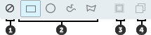
Figure 6.
- Window Select Disabled. Disable window selection. Allows
for fast clicking without the risk of dragging a mini window.
(HyperMesh only)
- Window Shape. Change the shape of the selection window when you drag your mouse.
- Intersection. Select entities that intersect the window.
Available for elements, lines, and surfaces.
(HyperMesh only)
- Only Select Visible. Only select visible entities.
Select Entities from the Entity Editor
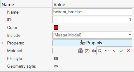
Figure 7.
-
Click
 , press ".", or press
Ctrl + Spacebar to select by typing names or IDs. While typing, the selection
search function provides live suggestions of:
, press ".", or press
Ctrl + Spacebar to select by typing names or IDs. While typing, the selection
search function provides live suggestions of:
- Entity names that contain the typed search terms (separated by space)
somewhere in their name.Tip: If you wish to treat spaces as characters instead of search term separators, turn on the Match Exact Phrase option in the Preferences dialog, located in .
- Entity IDs that begin with a numeric search term.
A live suggestions list will show partial matches for names and IDs while typing, up to a certain number (configurable in ). If the model contains more partial matches than listed in the suggestions list, click Browse More, or press Ctrl + Enter, to browse and select from the full partial match list.Tip: Live partial match suggestions are available for entity counts of up to 100,000. However, you can still select by typing names or IDs regardless of model size, and full match suggestions will be still provided and selectable. - Entity names that contain the typed search terms (separated by space)
somewhere in their name.
-
To confirm your selection, click
 .
.
-
To cancel your selection, click
 .
.
Select Set Segments
The following additional functionalities are available in the entity selector when editing the contents of a set segment.
- Use standard selection controls to append or deselect elements, facets, faces, or edges where the segments are defined.
- Click
 to reverse or align segment
directions using the Adjust Directions dialog. The reverse
function flips all or some segment directions simultaneously. The align function
is only available for segments defined on shell elements.Tip: When aligning segments on shell elements, you can manually specify a reference element to align to by toggling the switch from Auto to Reference mode.
to reverse or align segment
directions using the Adjust Directions dialog. The reverse
function flips all or some segment directions simultaneously. The align function
is only available for segments defined on shell elements.Tip: When aligning segments on shell elements, you can manually specify a reference element to align to by toggling the switch from Auto to Reference mode. - When selecting 3D elements, segments are added to their outside faces only,
based on the current display state.Tip: While selecting set segment contents, you can freely switch between supported selection types (for example: elements, facets, faces) and the current selections are converted accordingly.
The following restrictions and considerations apply when selecting set segment contents:
- A single set segment can contain either face (2D) segments, or edge (1D)
segments, but not a mixture of both.
- When using box selection, if a mixture of 1D/2D elements is detected, the 2D elements are given priority. Only the 2D elements inside the box are selected and any 1D elements are ignored.
- Switching the selection type between elements, faces, and facets is
supported, but some conversions might result in additional segments.
- Example 1: A single facet of a single floating 3D hex element is currently selected, and the selector is then switched from facets to elements. The selection is converted correctly from 1 facet → 1 element, and upon accepting the new selection, the resulting number of segments is now 6 since every exposed side of the selected 3D element gets a segment.
- Example 2: If the same 3D element is not floating but instead part of a displayed mesh, the resulting number of segments is less than 6 because only its currently exposed outside faces get a segment (hidden internal mesh faces do not get segments).
- When selecting faces or facets, advanced selection operations are available (for example: select adjacent, reverse, by face, by path, and so on) which rely on their underlying elements. As such, any advanced selection operation performed on faces or facets considers their current base elements as fully selected (including all outside faces of 3D elements). The same applies to saving and retrieving selections via the right-click menu.
- When selecting facets, performing graphical window selections of a large number of facets can have a significant performance cost. For such scenarios, using elements as the selection type is recommended for optimal performance.
Perform Extended Entity Selection
Use extended entity selection to find, filter, and select subsets of entities. Extended selections can be added to, removed from, or intersected with existing selections, and previous selections can be also saved and retrieved.
-
Open the Advanced Selection dialog in one of the following
ways:
- Click
 next to an entity selector.
 - Press Spacebar.
- Right-click in the modeling window and choose .
Use the drop-down menus at the top-left of the dialog to choose the extended selection mode (Add, Remove, or Intersect) and the selection method (options vary depending on entity type), then select a subset of entities.The process for selecting entities varies depending on the method.
Tip: The options in the context menu beneath Advanced (By Entity, By ID, etc. ) correlate to different selection methods in the Advanced Selection dialog. Choosing one of these options opens the dialog with the selected method. - Click
Extended Entity Selection Options
The following options are available for extended entity selection.
Context Menu Options
- Displayed
- Select all entities of the specified type currently displayed in the modeling window.
- Reverse
- Allows for a Boolean "not" to be performed on the currently displayed entities; all selected entities are removed from the mark; all entities which are not on the mark and are currently active are selected.
- All
- Select all entities of the specified type. The set to be added to the user mark includes entities displayed and those not displayed.
- Adjacent
- Select entities adjacent to the entities already selected.
- Attached
- Select entities by specifying an entity among a large group of continuously connected elements. HyperWorks includes the entities currently displayed that are attached to the entities already selected. Entities that are not displayed will not be selected although they may be attached to the entity selected.
- Face
- Select entities that are located on the same surface face as the previously selected entity. HyperWorks finds entities that are attached to each other without crossing a feature line. Attached, adjacent surfaces, nodes, or elements are progressively selected when the angle between them is less than or equal to the specified feature angle.
- By Dimension
- Select entities by dimension (0D, 1D, 2D, and 3D). You can select one or more of the dimensions available.
- Similar
- Select entities that are similar to the your current selection based on config.
- Clear Selection
- Remove all entities from your active selection.
- Save Selection
- Save the currently selected entities to a holding area known as the user mark.
- Retrieve Selection
- Retrieve previously saved entities from the user mark.
HyperMesh Advanced Selection Dialog Options
- By Assembly
- Select entities by assembly.
- By Block
- Select entities associated with one or more block entities.
- By Collector
- Select elements, lines, surfaces, loads, coordinate systems, vectors, equations, and points by collector.
- By Component
- Select entities by component.
- By Config
- Select elements by configuration and type. The element type is dependent on the template file.
- By Connector Group
- Select entities associated with one or more connector groups.
- By Domains
- Select entities associated with a morph domain.
- By Edge
- Select entities (nodes, elements) by surface edge. HyperWorks finds entities that are attached to each other without crossing a feature line. The feature line can be adjusted using the Angle slider. Attached, adjacent surfaces or elements are progressively selected when the angle between them is less than or equal to the specified feature angle.
- Click
 to
view more options.
to
view more options. - By Face
- Select entities that are located on the same surface face as the previously selected entity. HyperWorks finds entities that are attached to each other without crossing a feature line. The feature line can be adjusted using the Angle slider. Attached, adjacent surfaces, nodes, or elements are progressively selected when the angle between them is less than or equal to the specified feature angle.
- Click to
view more options.
- By Group
- Select entities by group.
- By Handles
- Select entities associated with morphing handles.
- By ID
- Select entities by typing in their ID numbers.
- By Include
- Select FE entities such as elements, loads, and groups that belong to
the selected include.Note: Includes created via the Model Browser are only valid for solvers that support them.
- By Laminate
- Select entities associated with one or more laminate entities.
- By Limits (3D)
- Using this method, selection propagates to all connected faces selected,
while excluding faces that are connected to the specified limit nodes.
Limit nodes must be selected first to enable the propagating faces
selector.Note: This method is only available when the selection type is faces or facets.
- By Line
- Pick lines in the modeling window. Entities associates with the lines are selected.
- By List
- Select entities from a list.
- By Material
- Select entities by material.
- By Morphing Volumes
- Select entities associated with morphing volumes.
- By Multibodies
- Select entities associated with one or more multibody entities.
- By Output Block
- Select the nodes, elements, comps, systs, groups and mats within an outputblock.
- By Part
- Select entities associated with a part.
- By Path
- Pick multiple nodes, lines, or elements and select all the nodes/lines/elements that fall in the closest connecting path. If you select two nodes on a free edge of some elements, the function tries to find the closest path along that free edge. This function uses the connectivity of the elements between the nodes, and thus requires the selected nodes to be part of a continuous shell mesh. Similarly, By Path for lines uses the connectivity of surfaces/solids and thus requires the selected lines to be surface/solid edges.
- By Ply
- Select entities associated with one or more ply entities.
- By Points
- Pick points in the modeling window. Entities associates with the points are selected.
- By Property
- Select entities by property.
- By Set
- Select the entities within a set.
- By Solid
- Pick solids in the modeling window. Entities associates with the solids are selected.
- By Surface
- Pick surfaces in the modeling window. Entities associates with the surfaces are selected.
- By Width
- Select surfaces by width, either by picking a sample surface or by specifying a range of values for the width.
HyperView Advanced Selection Dialog Options
All selection methods in the dialog include a visibility filter. This allows you to apply your settings to all entities in the model, regardless if they are displayed on the screen or not, or only the entities that are displayed.
In addition,HyperView is capable of entity binding changes between nodes, elements, and components - which provides you with easy selection. For example, when Nodes is specified on the entity selector, the By ID option allows you to select either By Node ID, By Element ID, or By Component ID.
- By ID
- Select entities by entering an ID number.
- By Type
- Select elements by configuration. You can select one or more of the various element configurations available.
- By Sets
- Select the entities within a set.
- By Contour
- Select entities by contour.
- By Sphere
- Allows you to select entities by entering location information for x, y, z and a user-defined radius.
Quick Advanced Selection
Use quick advanced selection to associate a preferred advanced selection method to different entity types. The advanced method becomes instantly accessible while holding the Alt key during any selection action.
Appending and deselecting while using quick advanced selection is also possible via Alt + Ctrl and Alt + Shift, respectively.
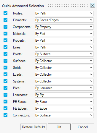
Figure 8.
Select Mesh Faces and Edges
Direct selection of mesh faces and edges is available in some tools, as well as their individual selection modes which are called Facets and FE Edges, respectively.
- When selecting faces, options are available to ignore mesh intersections, plot element boundaries, or restrict face selection to only shell or solid meshes.
- When selecting edges, options are available to ignore mesh intersections, plot elements, or restrict the edge selection to only free edges or full loops.
It is important to note that these special selection types are provided as conveniences and are not native HyperMesh entities (like nodes or elements are), and as such have the following restrictions and considerations:
- The topology of mesh faces and edges has to be calculated on-the-fly each time their selection is requested, so hovering or selecting large mesh areas can produce delays in calculating the resulting selection.
- When selecting faces or individual facets, advanced selection operations are available (for example: select adjacent, reverse, by face, by path, and so on) which rely on their underlying elements. As such, any advanced selection operation performed on faces or facets considers their current base elements as fully selected (including all outside faces of 3D elements). The same applies to saving and retrieving selections via the right-click menu.
- When selecting individual facets, performing graphical window selections of a large number of facets can have a significant performance cost. For such scenarios, choosing elements or nodes as the selection type is recommended for optimal performance.
- Switching the selection type from mesh faces and edges to their underlying nodes or elements is supported in all tools, however the reverse conversion (from faces or edges to nodes or elements) is only available in some tools.
Keyboard Shortcuts & Mouse Controls
Selection
| To do this | Press |
|---|---|
| Window select | Left Mouse Drag |
| Append selection | Ctrl + Left Mouse Click |
| Deselect | Shift + Left Mouse Click |
| Select displayed | Ctrl + A |
| Select all | Ctrl + Shift + A |
| Select adjacent | Ctrl + J |
| Select attached | Ctrl + T |
| Select similar (based on type and config if applicable) | Ctrl + M |
| Reverse selection | Ctrl + R |
| Open advanced selection | Spacebar |
| Quick advanced selection Configurable via Mouse Control Preferences |
Alt + Left Mouse Click |
| Adjust feature angle when selecting elements By Face or By Edge | Alt + Scroll |
| Edit | Double Mouse Click |
| Suspend snaps | Alt |
| Clear active selector | Backspace |
| Clear all guide bar selectors | Esc |
Entity Selector
| To do this | Press |
|---|---|
| Set to components/connectors | C |
| Set to elements | E |
| Set to laminates/lines/loads | L |
| Set to materials | M |
| Set to nodes | N |
| Set to plies/points/properties | P |
| Set to solids/surfaces/systems | S |
| Set to all | Esc + Esc |
| Selection search (Entity Editor only) | "." or Ctrl + Spacebar |
Select Entities Using Legacy Selectors
For older contexts, selection is performed via yellow entity selectors.
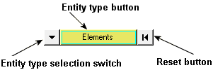
Figure 9.
An entity type in the plural form, such as "elements", indicates that you are able to select more than one entity from your model. An entity type in the singular form, such as "node", indicates that you can select only one entity from your model at a time.
When you need to define a plane by specifying a plane's normal vector, the selector allows you to select nodes one at a time by entering the node ID. Similar to other selectors, the active node is surrounded by a blue square.
Examples of this type of input collector include:

Figure 10. Plane normal vector definition using the global axis

Figure 11. Plane normal vector definition
Use the Extended Entity Selection Menu
-
Click the entity type button on the selector
 to access the extended entity
selection menu.
A pop-up menu containing the available selection techniques is displayed. This menu allows alternative methods for selecting elements of the specified entity type.Note: The options displayed on the extended entity selection menu are dependent upon the active input collector.
to access the extended entity
selection menu.
A pop-up menu containing the available selection techniques is displayed. This menu allows alternative methods for selecting elements of the specified entity type.Note: The options displayed on the extended entity selection menu are dependent upon the active input collector.
- By right-clicking in the modeling window.
- In the Advanced Selection dialog by clicking on an entity selector.
Change the Entity Type
-
Click the entity type selection switch
 to access a pop-up menu of
possible entity types.
to access a pop-up menu of
possible entity types.
- Select the type that you want to use.
Reset the Selector
Card Filter
Use the Card Filter to restrict the list of entities displayed when you click the entity selector.
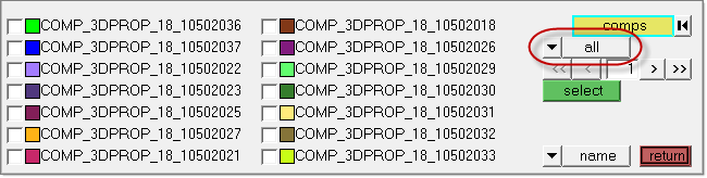
Figure 12. Card Filter. Card Filter is outlined in red.
Some panels present a list of entities when you click their Entity Selector button instead of the Extended Entity Selection options.
| Assembly | Beamsection collector | Blocks |
| Component | Contact surfaces | Control volume |
| Curves | Ddvals | Groups |
| Laminates | Load collector | Load steps |
| Material | Multibodies | Plies |
| Plots | Property | Sensors |
| Sets | Shapes | System collector |
| Tags | Titles | Vector collector |

Figure 13.
This displays a read-only text field adjacent to the Card Filter control. Click card to open a pop-up window that lists all of the cards defined in your model for the selected type of entity, and pick the card that you wish to filter by.
Once selected, only entities with the chosen card type will display in the entity list on the panel.
To remove the filter, simply use the switch to select all, displaying all entities regardless of card association, or no card, displaying only those entities that do not have a card at all.