Cable Pin Numbers
Adding a voltage source to a cable requires understanding of the conductor to cable conductor pin relation and rules.
Rules regarding pin numbering
- Pin 0 always corresponds to the geometry or meshed model.
- Use increasing pin numbers starting at the innermost conductor of a simple cable type and counting towards the outside.
- Use increasing pin numbers in the order of the cross section definition inside the cable bundle.
Pin numbering used for cable modelling can best be described by examples. The following set of examples illustrate how the pin numbering is set.
Example 1: An insulated single conductor above ground
The model consists of the following:
- Sub-circuit 1
- Single core (Pin 1) with geometry or meshed model as reference (Pin 0).
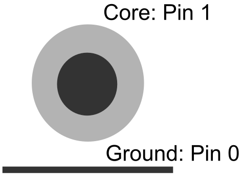
Figure 1. An insulated single conductor above ground.
Example 2: Coaxial cable above ground
The model consists of the following:
- Sub-circuit 1
- Outside of shield (Pin 2) with geometry or meshed model as reference (Pin 0).
- Sub-circuit 2
- Coaxial core (Pin 1) with the inside of shield (Pin 2) as reference.

Figure 2. A coaxial cable above ground.
Example 3: Ribbon cable with n cores
The model consists of the following:
- Sub-circuit 1
- Cores 1..n (excluding Pin i) with Pin i as reference.
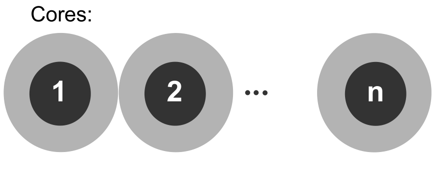
Figure 3. A ribbon cable with n cores.
Example 4: Complex bundle (mixed) cable
The model consists of the following:
- Bundle1 (shielded)
- Single1, Single2, Coax1, Ribbon1, Coax2, Bundle2 and Bundle3.
- Ribbon1
- 3 cores.
- Bundle2 (not shielded)
- Single3, Single4 and Single5.
- Bundle3 (shielded)
- Single6 and Coax3.
Regarding the loading or excitation for sub-circuit 2, in this example it is only allowed between 1, 2, the outside of the shield of coaxial cable 4, 5, 6, 7, the outside of the shield of coaxial cable 9, 10, 11, 12 and the outside of the shield of the coaxial cable 16 and the inside of the shield of the bundle 17.
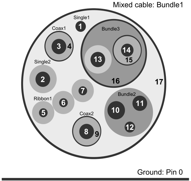
Figure 4. Complex (mixed) cable bundle with single conductors, ribbon cables and coax.
| Sub-circuit number | Pin numbers | Reference pin |
|---|---|---|
| 1 | 17outside | 0 (geometry/meshed model). |
| 2 | 1, 2, 4outside, 5, 6, 7, 9outside, 10, 11, 12 , 16outside | 17inside |
| 3 | 3 | 4inside |
| 4 | 8 | 9inside |
| 5 | 13, 15outside | 16inside |
| 6 | 14 | 15inside |