演習1:システム定義の作成と使用
本演習では、元のシステムMDLファイルからシステム定義を生成する方法について学習します。
- *DefineSystem()
- *System()
- *SetSystem()
- *Attachment()
本演習では、これらのアクションを実施します:
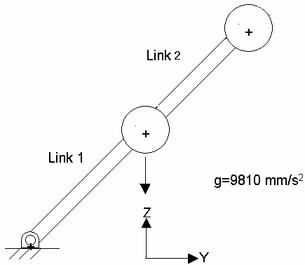
図 1. 二重振子の詳細図
- チュートリアルMV-1060:MDLステートメントを用いた振子モデルの構築からの振子モデルを修正し、sys_pendu_mdlというシステム定義を作成します。
- このシステム定義を使って、別の振子をモデルに追加し、図 1に示すような二重振子のモデルを作成します。
- ベースモデルをdoublependulum.mdlとして保存します。
- 過渡応答の動力学シミュレーションを実行し、アニメーションを表示させます。
図 1. 二重振子の詳細図
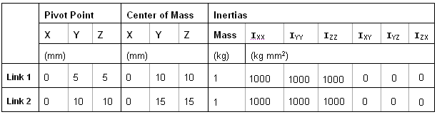
図 2. 二重振子のプロパティ一覧
システム定義の作成
このステップでは、チュートリアルMV-1060:MDLステートメントを用いた振子モデルの構築からのMDLモデルファイルを使ってシステム定義を作成します。
MDLファイルの手動によるオーサリングでシステム定義を追加
このステップでは、システム定義を含むMDLファイルを書き、それを数度にわたってインスタンス化します。
-
MotionViewでMDLファイルを開きます。特に、Projectブラウザ内にリストされているFirst Pendulum SystemファイルとSecond Pendulum Systemファイルに着目してモデルを確認します。
 (System)アイコンの下に、小さな'手'のマークが付いています。これは、両方のシステムが単一の定義を有しているShared Definition(共有定義)と呼ばれる特徴です。
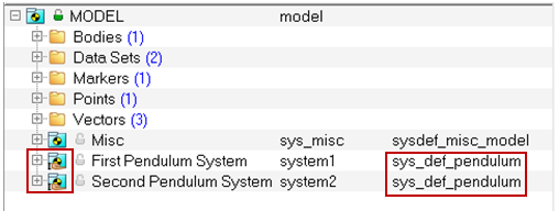
図 3. -
すべてのインスタンスに変更を加えます。
-
OptionsダイアログでBuild Model(ツリーの下部)をクリックします。
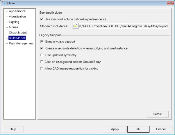
図 4.
-
OptionsダイアログでBuild Model(ツリーの下部)をクリックします。
-
MotionSolveの実行と結果のポスト処理を行います。
-
 (Run)パネルボタンをクリックします。
- パネル内で、End timeを1.0に、Print intervalを0.01と指定します。
- Run ボタンをクリックします。
-