Bearings
The MotionSolve bearing API statements help you model analytical bearing elements.
- Angular contact ball bearing
- Cylindrical roller bearing
- Deep groove ball bearing
- Spherical roller bearing
- Tapered roller bearing
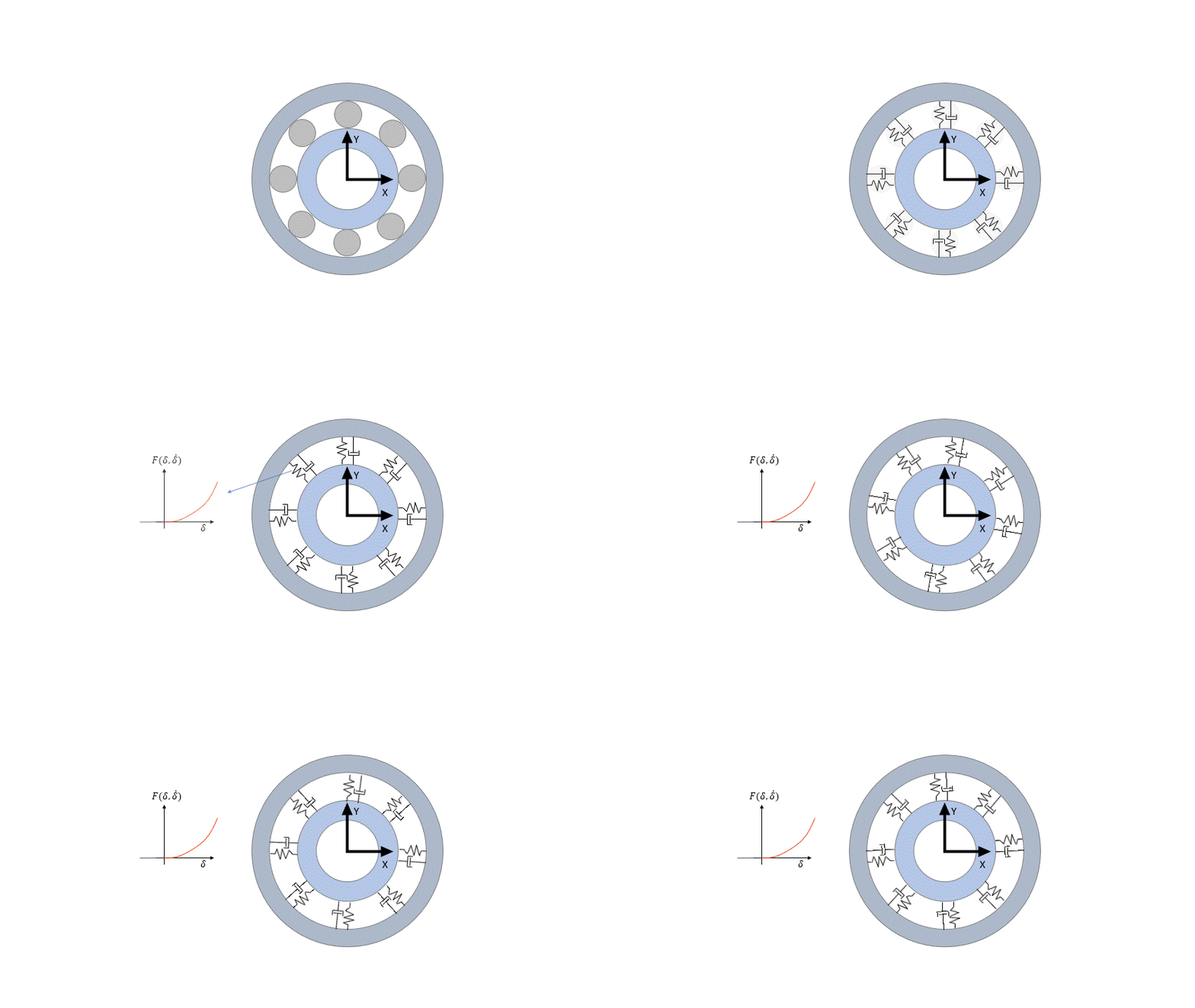
Each bearing consists of an inner and outer raceway that are defined as rigid bodies. Both raceways are connected to each other by a non-linear spring-damper system that represents the balls/rollers between the raceways. The spring-damper system is defined analytically using the Hertzian approach for point contact (balls) and the Palmgren formula for line contact (rollers). Its stiffness and damping properties are dependent on the relative position and velocity between the raceways. In the initial resting position, the local z-axis of the inner/outer race points along the shaft and the origin of the local frame is at the center of mass.

Figure 1. Description of the analytical bearing
The bearing’s cage and rolling elements are included as one rigid body. Its mass and inertia is approximated using the rolling element geometries. This rigid body helps estimate the overall weight of the bearing as well visualize the rotation of the rollers.
Most of the machinery bearing’s input arguments can be extracted from catalogues and tables provided by bearing OEMs. Not all internal geometry parameters are provided in these tables directly, but instead need to be extracted from CAD geometry files that are provided by the OEMs.
The online OEM’s calculators can be used to extract many of the needed parameters, such as the type and the viscosity of bearing lubricants, or any calculation factor used for the friction torque calculation.